High flexibility, kink resistant catheter shaft

a flexible, kink-resistant, catheter technology, applied in the direction of balloon catheters, catheters, coatings, etc., can solve the problems of dangerously increasing the sheer force of the vascular system, increasing the stiffness of the tubular membrane, and reducing the trackability, so as to facilitate the free movement of the wire helix, reduce the tendency of the tubular membrane, and promote the control of hinging

Active Publication Date: 2018-01-18
PERFUZE LTD
View PDF8 Cites 16 Cited by
  • Summary
  • Abstract
  • Description
  • Claims
  • Application Information

AI Technical Summary

Benefits of technology

[0006]The present disclosure is directed toward catheter shaft designs that are more flexible than conventional shafts and that demonstrate a unique set of properties such as relative independence of catheter diameter and stiffness, catheter diameter and trackability, and catheter stiffness and kink resistance. The catheter shafts described below permit the passage of larger diameter catheters through tortuous vascular anatomy and to more distal vascular anatomy, while providing improved resistance to compression or ovalization during bending. This increase in flexibility is coupled with an improved kink resistance for a given catheter diameter.
[0008]Controlled hinging (e.g., pleating or corrugating) of the tubular membrane during bending reduces the tendency of the tubular membrane to buckle or kink at a focal bending point. In some embodiments, the tubular membrane is supported by opposing inner and outer coils as described above, which can promote the controlled hinging. In some embodiments, the tubular membrane is supported by only an outer coil or an inner coil that is affixed to the tubular membrane by an ultra-thin layer of a suitable plastic, such as Kynar, that does not restrict the pleating of the tubular membrane.
[0009]Some aspects of the disclosure are directed toward a highly flexible, kink resistant catheter with floating tubular support. The catheter can include an elongate tubular body having a proximal end, a distal end and a central lumen. The tubular body can include an inner tubular layer surrounding the lumen. A helical support can be carried concentrically over the inner layer. Adjacent loops spaced axially apart. The pitch of the adjacent loops can be varied to adjust for flexibility and pushability. An outer tubular layer can be carried concentrically over the helical support. The inner layer and the outer layer are bonded together in the space between adjacent loops of the tubular support to form a helical channel and the helical support is floating unbonded within the helical channel, e.g., the tubular support is not molecularly or physically attached to the inner layer or the outer layer. The cross sectional area of the helical channel can be varied from an area just larger than the wire cross sectional area to an area up to 10× larger than the wire cross sectional area in order to facilitate free movement of the wire helix.

Problems solved by technology

However, there is generally a trade-off between the features of catheter diameter, trackability, flexibility, and kink resistance.
An increase in catheter diameter tends to increase its stiffness, which lowers its trackability and may dangerously increase vascular sheer forces.
However, when the resulting reinforced tube is flexed, a great deal of energy goes into stretching the plastic matrix on the outside curve and compressing the plastic matrix on the inside curve of the tube.
Further, varying the durometer creates potential kinking points at the durometer transition points.
This conventional construction also provides limited force transmission or pushability due to buckling or ovalization of the distal shaft.

Method used


Image

  • High flexibility, kink resistant catheter shaft
  • High flexibility, kink resistant catheter shaft
  • High flexibility, kink resistant catheter shaft

Examples


example embodiments

[0108]The following example embodiments identify some possible permutations of combinations of features disclosed herein, although other permutations of combinations of features are also possible.

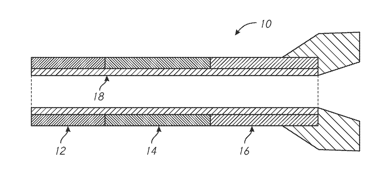
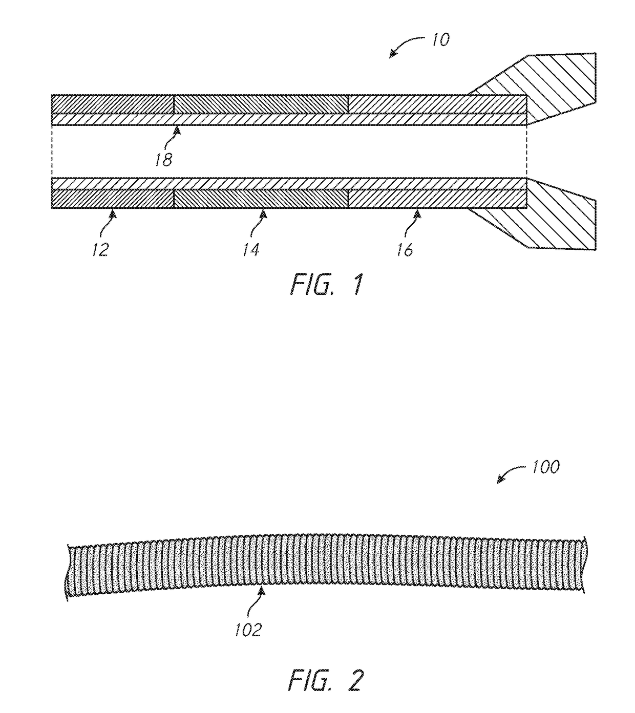
[0109]1. A highly flexible, kink resistant catheter with floating tubular support, comprising:[0110]an elongate tubular body, having a proximal end, a distal end and a central lumen, the tubular body comprising:[0111]an inner tubular layer surrounding the lumen;[0112]a helical support, carried concentrically over the inner layer and having adjacent loops spaced axially apart; and[0113]an outer tubular layer, carried concentrically over the helical support;[0114]wherein the inner layer and the outer layer are bonded together in the space between adjacent loops of the tubular support to form a helical channel and the helical support is floating unbonded within the helical channel.

[0115]2. A highly flexible catheter as in Embodiment 1, wherein at least one of the inner and outer tubular layers...


PUM

PropertyMeasurementUnit
lengthaaaaaaaaaa
lengthaaaaaaaaaa
lengthaaaaaaaaaa

Abstract

An enhanced flexibility catheter shaft having an elongate flexible body with a proximal end, a distal end, and at least one lumen extending therethrough. A distal, flexible section on the body has a ribbed or corrugated tubular membrane having at least a first reinforcement structure, such as a first helical support, on a radially exterior or interior surface of the membrane and optionally a second reinforcement structure, such as a second helical support, on the other of the radially interior or exterior surface of the membrane

Description

INCORPORATION BY REFERENCE TO ANY PRIORITY APPLICATIONS[0001]This application claims the benefit of U.S. Provisional Application No. 62 / 361984, filed Jul. 13, 2016, which is hereby incorporated by reference in its entirety herein.[0002]Any and all applications for which a foreign or domestic priority claim is identified in the Application Data Sheet as filed with the present application are hereby incorporated by reference under 37 CFR 1.57.BACKGROUNDField[0003]The present disclosure relates to a flexible catheter for endovascular procedures.Description of the Related Art[0004]Nearly all endovascular procedures require the use of flexible catheters, for example, to deliver contrast injection, to deliver implantable devices, perform vascular procedures, or to aspirate. Due to the tortuous nature of the vasculature, it is important for catheters to be flexible enough to travel through vessels without excessive force. However, there is generally a trade-off between the features of cath...

Claims


Application Information

Patent Timeline
Patent Type & Authority Applications(United States)
IPC IPC(8): A61M25/00A61F2/95A61M25/10
CPCA61M25/0045A61M25/0054A61M25/10A61F2/95A61M25/0068A61M25/001A61M25/0012A61M25/0053A61M25/0052A61M25/005A61M2025/0059A61M25/0013A61M25/008A61M25/0108A61M25/09
Inventor CRAGG, ANDREW H.LOGAN, JOHNARP, SCOTT
Owner PERFUZE LTD
Why Eureka
Try Eureka