
Vehicle warning control apparatus

a technology for vehicle warning and control apparatus, which is applied in the direction of pedestrian/occupant safety arrangement, instruments, and tractors, etc., can solve the problems of inability to sound, horn melt, and possibility that nobody passes by for a long time near the stopped vehicle, so as to prolong the non-operation period, reduce the number of sounding horns, and reduce the effect of horn mel

Active Publication Date: 2018-01-18
TOYOTA JIDOSHA KK
View PDF0 Cites 13 Cited by
  • Summary
  • Abstract
  • Description
  • Claims
  • Application Information

AI Technical Summary

Benefits of technology

The present invention relates to a vehicle warning control apparatus that can alert surrounding people when the driver is in an abnormal state. The main technical effect of the invention is to decrease the ratio of the sounding time of the horn per unit time, which helps to suppress heat generation and increase the notification with the horn for an extended period of time. This results in an increased rescue ratio for the driver. Additionally, the invention includes a feature that allows for intermittent sounding of the horn, which further helps to control the notification to surrounding people and allows for continued notification during vehicle deceleration or stoppage.

Problems solved by technology

However, when a general horn used for vehicles are sounded for a long period of time, there is a possibility that the horn melts due to heat generation of internal parts and eventually becomes incapable of sounding.
However, for example, in a case where the driver falls into the abnormal state while driving on a quiet road and the vehicle stops, there is a possibility that nobody passes by near the stopped vehicle for a long period of time.
In such a case, there is a possibility that the horn stops sounding before some pedestrian or other vehicle passes by near the vehicle.
In this case, it becomes impossible to notify surrounding people of the driver being in the abnormal state by sounding the horn, and therefore a rescue timing of the driver will be delayed.
When such a horn is sounded for a long period of time, internal parts thereof generate heat, and the horn eventually becomes incapable of sounding owing to exceeding a tolerance limit by the heat generation.
When the horn stops sounding owing to exceeding the tolerance limit thereof, it becomes impossible to notify of the driver's abnormal state using the horn.
However, people may not be always in the region where the sounding of the horn can be heard.
On the other hand, the horn becomes incapable of sounding due to the heat generation when the horn is sounded for a long period of time.

Method used


Image

  • Vehicle warning control apparatus
  • Vehicle warning control apparatus
  • Vehicle warning control apparatus

Examples


modification example 1

of the Sounding Pattern

[0117]Next, a modification example 1 of the sounding pattern will be explained. FIG. 5 shows the modification example 1 of the sounding pattern. In this modification example 1, the horn intermittent sounding period D1 of each of the patterns 1 to 4 is equal, whereas the horn non-operating period D2 of each of the patterns 1 to 4 is different. In this case, the horn non-operating period D2 is set in such a manner that the horn non-operating period D2 is the shortest in the pattern 1, and becomes longer in the order of the pattern 2, the pattern 3, and the pattern 4. Therefore, in this modification example 1, as is the case with the embodiment, the ratio of the sounding time of the horn 92 per unit time decreases with the time elapsed since the horn 92 starts sounding.

modification example 2

of the Sounding Pattern

[0118]Next, a modification example 2 of the sounding pattern will be explained. FIG. 6 shows the modification example 2 of the sounding pattern. In this modification example 2, the number of sounding of the horn 92 in the horn intermittent sounding period D1 is the same as the number of sounding of the horn 92 in the embodiment, whereas, the horn non-operating period D2 is set in such a manner that the horn non-operating period D2 is the shortest in the pattern 1, and becomes longer in the order of the pattern 2, the pattern 3, and the pattern 4. Therefore, in this modification example 2, as is the case with the embodiment, the ratio of the sounding time of the horn 92 per unit time decreases with the time elapsed since the horn 92 starts sounding.

modification example 3

of the Sounding Pattern

[0119]Next, a modification example 3 of the sounding pattern will be explained. FIG. 7 shows the modification example 3 of the sounding pattern. In this modification example 3, a horn sounding period D1′ showing one successive sounding time of the horn 92 is set in place of the horn intermittent sounding period D1. One cycle of a horn sounding pattern is composed of the horn sounding period D1′ and the horn non-operating period D2. The horn 92 sounds intermittently by this horn sounding pattern being repeated.

[0120]The horn sounding period D1′ is the longest in the pattern 1, and becomes shorter in the order of the pattern 2, the pattern 3, and the pattern 4. On the other hand, the horn non-operating period D2 is the shortest in the pattern 1, and becomes longer in the order of the pattern 2, the pattern 3, and the pattern 4. Therefore, in this modification example 3, as is the case with the embodiment, the ratio of the sounding time of the horn 92 per unit ti...


PUM


Abstract

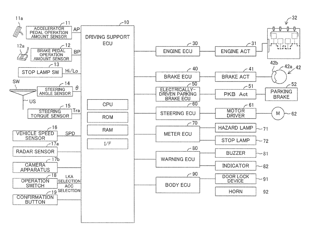
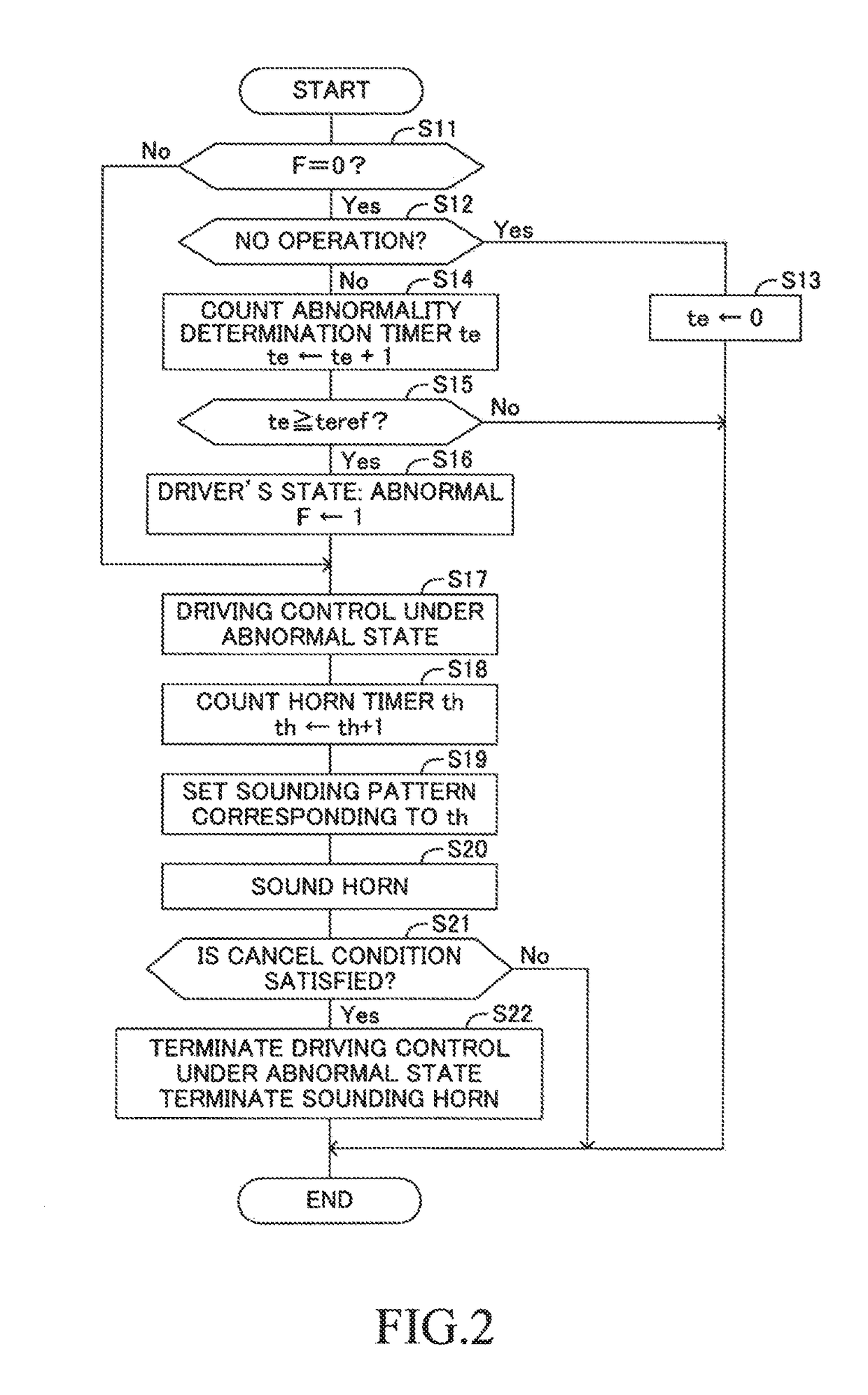
When a driving support electronic control unit (DSECU) determines that a driver of a vehicle is in an abnormal state where the driver loses an ability to drive the vehicle, the DSECU starts driving control under the abnormal state to decelerate the vehicle until the vehicle stops and to sound a horn. In this case, the DSECU measures an elapsed time since the horn starts sounding with a horn timer th, and sets a sounding pattern corresponding to the elapsed time measured. This sounding pattern is set in such a manner that a ratio of a sounding time of the horn per unit time decreases as the elapsed time since the horn starts sounding become longer. Thereby, it becomes possible to properly notify that the driver is in the abnormal state using the horn.

Description

CROSS-REFERENCE TO RELATED APPLICATIONS[0001]This application claims priority to Japanese Patent application No. 2016-137303 filed Jul. 12, 2016, which is incorporated herein by reference in its entirety including the specification, drawings, and abstract.TECHNICAL FIELD[0002]The present disclosure relates to a vehicle warning control apparatus for sounding a horn of a vehicle when a drive has fallen into an abnormal state in which the driver loses an ability to drive the vehicle.BACKGROUND ART[0003]An apparatus has conventionally been proposed which determines whether or not a driver has fallen into an abnormal state where the driver loses an ability to drive a vehicle (for example, a drowsy driving state, a mental and physical failure state, and the like), and decelerates the vehicle when the driver is determined to be in such an abnormal state (for example, refer to Japanese Patent Application Laid-Open (kokai) No. 2009-73462.).[0004]It should be noted that hereinafter an “abnorm...

Claims


Application Information

Patent Timeline
Patent Type & Authority Applications(United States)
IPC IPC(8): B60K28/06B60T8/1763B60K31/00B60T17/18G08G1/16B60T8/172B60Q1/00B60R21/00B60W50/14
CPCB60K28/066B60K31/0008B60T17/18B60T8/172B60T8/1763B60W2550/148B60K31/00B60Q1/00B60R21/00B60W2050/143G08G1/16B60T7/042B60T7/14B60T7/22B60Q5/005B60T13/662B60T13/74B60T17/22B60W50/14B60K28/06B60W40/08B60W2040/0818B60W2552/40B60W2540/225G08B21/02B60W2540/26
Inventor TAKANO, MASAKI
Owner TOYOTA JIDOSHA KK
Learn More