Power supply device for vehicle and method of controlling the same

a technology for power supply devices and vehicles, applied in the direction of electric devices, gas pressure propulsion mountings, resistance welding apparatuses, etc., can solve the problems of increasing the weight of vehicles, devices being provided in a fixed manner, battery cannot be charged at a different place, etc., and achieve the effect of improving energy efficiency

Inactive Publication Date: 2007-02-08
TOYOTA JIDOSHA KK
View PDF24 Cites 69 Cited by
  • Summary
  • Abstract
  • Description
  • Claims
  • Application Information

AI Technical Summary

Benefits of technology

[0018] An object of the present invention is to provide a power supply device for a vehicle that has an electric storage device mounted thereon, that has improved energy efficiency, and that can be driven for a long time without the need of refueling.

Problems solved by technology

In other words, the charging device being provided in a fixed manner is disadvantageous in that the battery cannot be charged at a place other than the place where the charging device is provided in a fixed manner.
In contrast, if the charging device is mounted on the vehicle, there exists a problem of increase in vehicle weight.
However, the Japanese Patent Laying-Open No. 08-126121 relates to an electric vehicle having two drive motors mounted on the left and right sides or the front and rear sides thereof, and hence the disclosure cannot be applied as it is to the hybrid vehicle.
Furthermore, a hybrid vehicle commercially available at present has a storage battery with small capacity, and hence even if the battery can be charged at home, an amount of energy to be supplied at that time is small.
Therefore, refueling with petrol is frequently required.
However, the capacity of the storage battery is so small that, when a running route includes a long downslope, power generated by regenerative braking is discarded as heat, once a state of charge of the storage battery reaches a prescribed value.

Method used


Image

  • Power supply device for vehicle and method of controlling the same
  • Power supply device for vehicle and method of controlling the same
  • Power supply device for vehicle and method of controlling the same

Examples


first embodiment

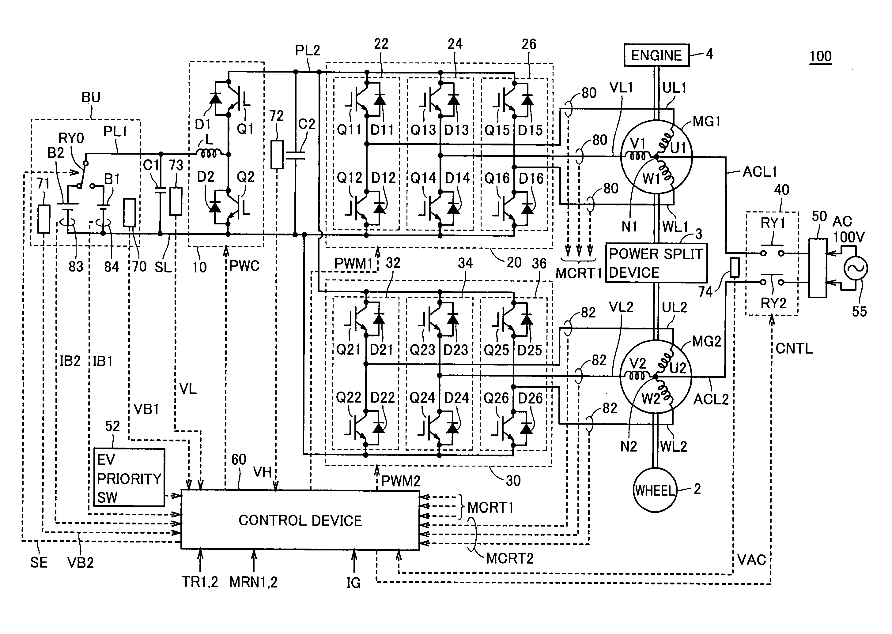
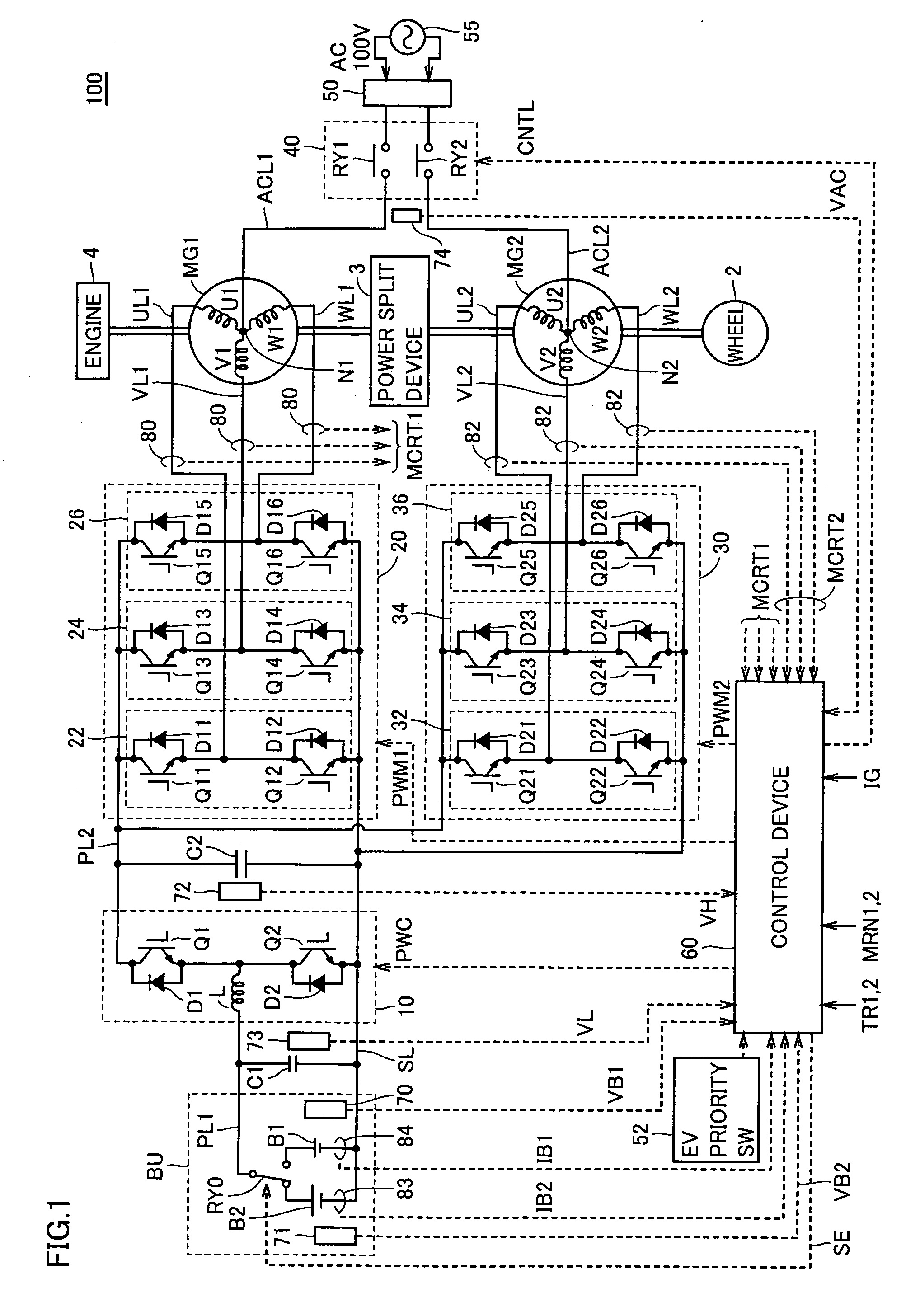
[0056]FIG. 1 is a schematic block diagram of a vehicle according to a first embodiment of the present invention.

[0057] Referring to FIG. 1, vehicle 100 includes a battery unit BU, a voltage step up converter 10, inverters 20, 30, power supply lines PL1, PL2, a ground line SL, U-phase lines UL1, UL2, V-phase lines VL1, VL2, W-phase lines WL1, WL2, motor generators MG1, MG2, an engine 4, a power split device 3, and a wheel 2.

[0058] Vehicle 100 is a hybrid vehicle that uses a motor and an engine in combination for driving the wheel.

[0059] Power split device 3 is a mechanism connected to engine 4 and motor generators MG1, MG2 for distributing motive power among them. For example, a planetary gear mechanism having three rotary shafts of a sun gear, a planetary carrier, and a ring gear may be used for the power split device. The three rotary shafts are connected to rotary shafts of engine 4, motor generators MG1, MG2, respectively. For example, engine 4 and motor generators MG1, MG2 ca...

second embodiment

[0157] In the second embodiment, battery unit BU is replaced with a battery unit BU1, in the configuration of FIG. 1. Other configurations are similar to those in the first embodiment, and hence the description thereof will not be repeated.

[0158]FIG. 11 is a circuit diagram showing a configuration of battery unit BU1 used in the second embodiment.

[0159] Referring to FIG. 11, battery unit BU1 includes batteries B1, B2 serving as electric storage devices whose negative electrodes are connected to each other, system main relays SMR1-SMR3 connecting battery B1 to the vehicle load, voltage sensors 70, 71 measuring voltages of batteries B1, B2, respectively, current sensors 84, 83 measuring currents of batteries B1, B2, respectively, and a DC / DC converter 200 connected between battery B1 and battery B2, and capable of transferring electric power bidirectionally. The combination of batteries B1, B2 is similar to that described in the first embodiment, and hence the description thereof wi...


PUM

PropertyMeasurementUnit
electric poweraaaaaaaaaa
alternating voltageaaaaaaaaaa

Abstract

A power supply device for a vehicle includes a battery serving as a first electric storage device, a battery serving as a second electric storage device, a motor generator driving a wheel, a selection switch selecting one of the first and second electric storage devices and connecting the selected electric storage device to the motor generator, and a control device controlling switching of the selection switch in accordance with a state of charge of each of the first and second electric storage devices. In the case where the selection switch selects the first electric storage device, when charging is performed and the state of charge of the first electric storage device becomes higher than a first prescribed level, the control device instructs the selection switch to select the second electric storage device.

Description

[0001] This nonprovisional application is based on Japanese Patent Application No. 2005-229849 filed with the Japan Patent Office on Aug. 8, 2005, the entire contents of which are hereby incorporated by reference. BACKGROUND OF THE INVENTION [0002] 1. Field of the Invention [0003] The present invention relates to a power supply device for a vehicle, and particularly to a power supply device for a vehicle, the power supply device having two electric storage devices. [0004] 2. Description of the Background Art [0005] In recent years, attention has been focused on an electric vehicle and a fuel-cell vehicle that use a motor in driving a wheel, and a hybrid vehicle that uses a motor and an engine in combination, and other vehicles, as an environmental-friendly vehicle. [0006] For example, an electric vehicle requires a charging device for charging a battery. The charging device may be mounted on a vehicle, or provided at a certain location in a fixed manner. [0007] In the case where the...

Claims


Application Information

Patent Timeline
Patent Type & Authority Applications(United States)
IPC IPC(8): B23K11/24B60K6/442B60L50/16B60W10/18B60W10/26B60W20/00H02J7/00H02P5/74H02P27/06
CPCB60L7/06Y02T90/14B60L7/22B60L11/123B60L11/14B60L11/1812B60L11/1814B60L11/1816B60L11/1861B60L11/1864B60L15/007B60L2220/14B60L2220/54Y02T10/6217Y02T10/641Y02T10/7005Y02T10/7044Y02T10/7061Y02T10/7077Y02T90/127B60L7/14Y02T10/7072B60L53/22B60L50/61B60L50/16B60L53/24B60L58/12B60L58/21Y02T10/62Y02T10/64Y02T10/70Y02T90/12
Inventor NAKAMURA, MAKOTOOYOBE, HICHIROSAIYANO, TSUYOSHI
Owner TOYOTA JIDOSHA KK
Why Eureka
Try Eureka