Method of using low-strength proppant in high closure stress fractures

a proppant and high closure stress technology, applied in the direction of fluid removal, chemistry apparatus and processes, borehole/well accessories, etc., can solve the problem that the proppant particulate volume cannot withstand fracture closure, reduce the likelihood of partial or complete fracture closure, and prevent optimal performan

Active Publication Date: 2018-01-18
HALLIBURTON ENERGY SERVICES INC
View PDF4 Cites 8 Cited by
  • Summary
  • Abstract
  • Description
  • Claims
  • Application Information

AI Technical Summary

Problems solved by technology

Thus, the fracture porosity is closely related to the strength of the placed proppant particulates and often tight proppant packs are unable to produce highly conductive channels within a fracture, while reducing the volume of the proppant particulates is unable to withstand fracture closures.
The use of proppant pillars, therefore, may reduce the likelihood of partial or complete fracture closure.
While proppant pillars can overcome certain issues associated with tight proppant packs, in practice several issues may prevent their optimal performance.
For example, proppant pillars of low-strength proppant, such as silica sand, are not conventionally used in high closure stress fractures, or a fracture having a closure pressure exceeding about 8,000 psi, due to their inability to withstand such pressure.
Unfortunately, high strength proppants typically cost more than low strength proppants; thus, increasing costs associated with the hydraulic fracturing of high closure stress fractures.
In addition, although proppant pillars provide greater conductivity channels for fluid flow, the problems associated with formation and migration still persist.
For example, fines are generated when proppant particulates are crushed due to their inability to withstand fracture closure stress.
Regardless of how the fines are formed, fine migration decreases well performance even in fractures having proppant pillars.

Method used


Image

  • Method of using low-strength proppant in high closure stress fractures
  • Method of using low-strength proppant in high closure stress fractures
  • Method of using low-strength proppant in high closure stress fractures

Examples


Embodiment Construction

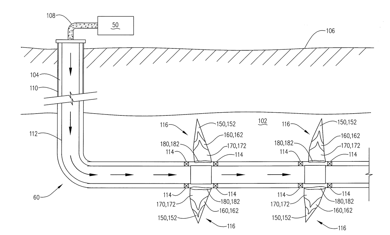
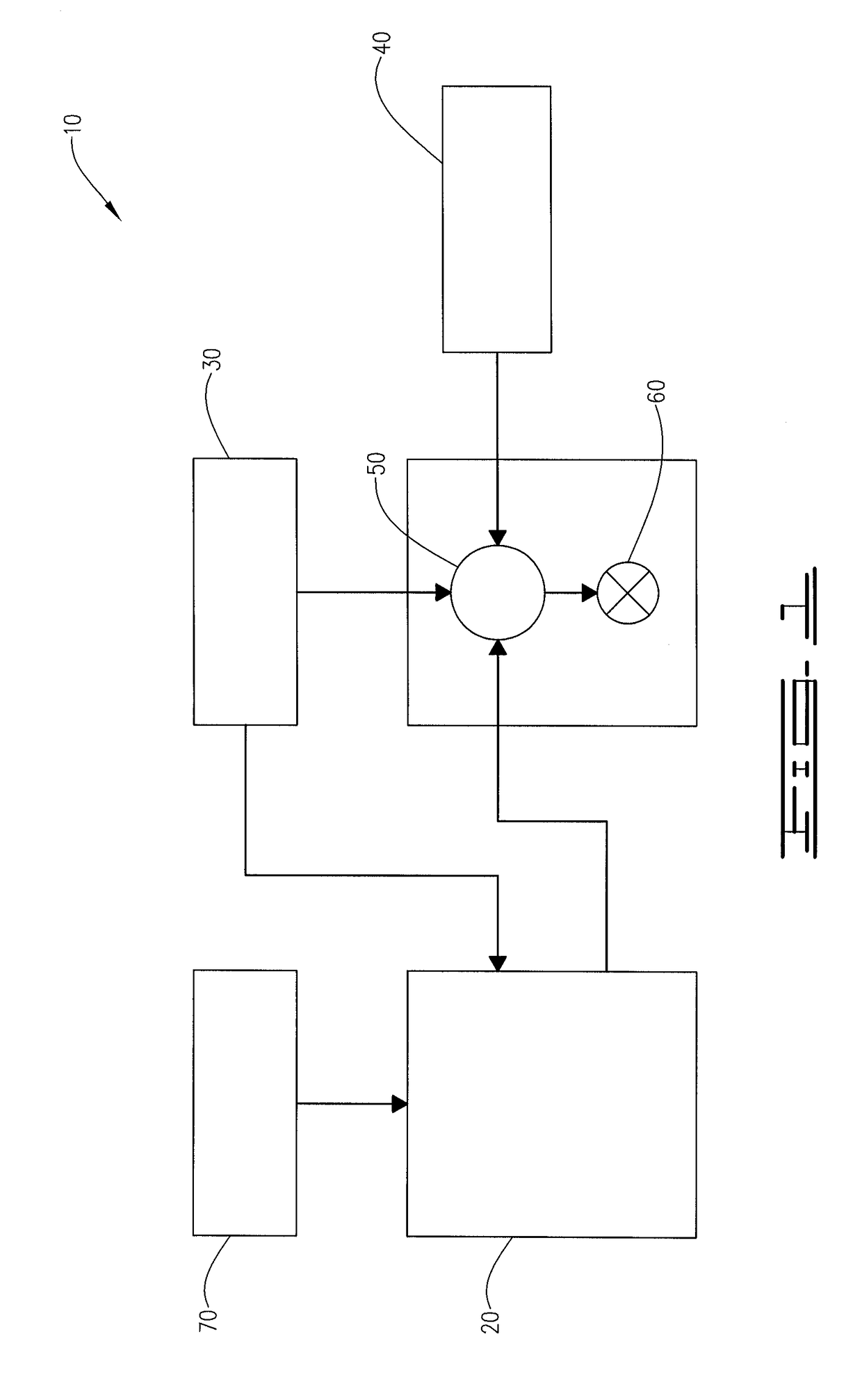
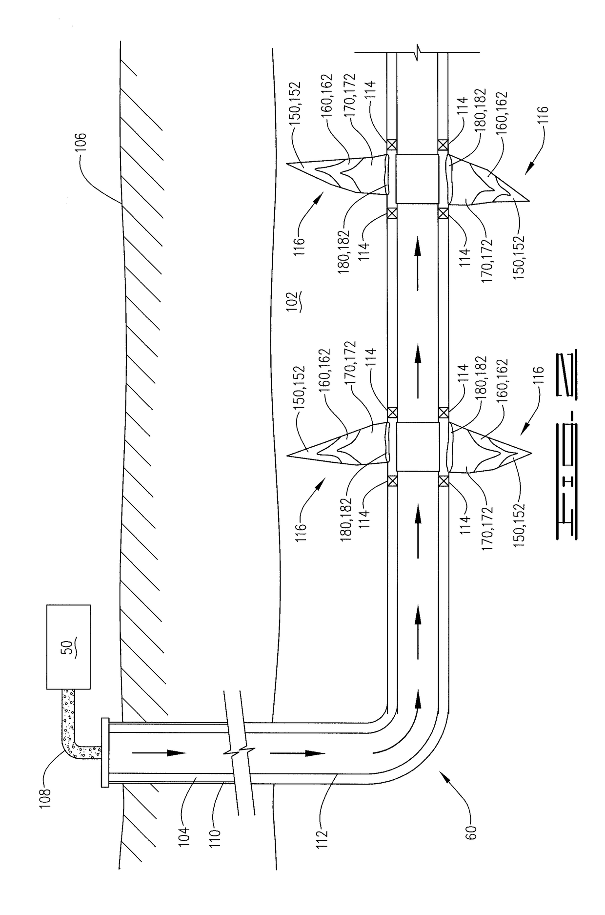
[0012]The present disclosure may be understood more readily by reference to the following detailed description as well as to the examples included therein. For simplicity and clarity of illustration, where appropriate, reference numerals have been repeated among the different figures to indicate corresponding or analogous elements. In addition, numerous specific details are set forth in order to provide a thorough understanding of the embodiments described herein. However, it will be understood by those of ordinary skill in the art that the embodiments described herein can be practiced without these specific details. In other instances, methods, procedures and components have not been described in detail so as not to obscure the related relevant feature being described. Also, the description is not to be considered as limiting the scope of the embodiments described herein. The drawings are not necessarily to scale and the proportions of certain parts have been exaggerated to better ...


PUM

PropertyMeasurementUnit
closure pressureaaaaaaaaaa

Abstract

Of the methods provided herein, is a method comprising: introducing into a fracture within a subterranean formation a first treatment fluid comprising uncoated first proppant particulates; introducing into the fracture a second treatment fluid comprising non-hardenable coated second proppant particulates to form a proppant pack; and introducing into the fracture a third treatment fluid comprising hardenable coated third proppant particulates intermittently between a spacer fluid to form pillars.

Description

FIELD[0001]The present disclosure relates to enhancing the production of hydrocarbons from a subterranean formation and, more particularly, to an improved method of placing proppant into a subterranean formation.BACKGROUND[0002]To produce oil or gas from a reservoir, a well is drilled into a subterranean formation, which may be the reservoir or may be adjacent to the reservoir. A subterranean well includes a wellhead and at least one wellbore from the wellhead penetrating the earth. Typically, a wellbore must be drilled thousands of feet into the earth. Generally, as the depth of the formation increases, the static pressure and temperature of the formation increases.[0003]Subterranean wells (e.g., hydrocarbon producing wells, water producing wells, or injection wells) are often stimulated by hydraulic fracturing treatments. In traditional hydraulic fracturing treatments, a treatment fluid, which may also function simultaneously, or subsequently as a carrier fluid, is pumped into a p...

Claims


Application Information

Patent Timeline
Patent Type & Authority Applications(United States)
IPC IPC(8): C09K8/80C09K8/62E21B43/267E21B43/26
CPCC09K8/805C09K8/80C09K8/62E21B43/267C09K2208/08E21B43/26
Inventor SUZART, JOAO WALTER PEREIRABERTRAND, CLARENCE JOHNSABHAPONDIT, ANUPOM
Owner HALLIBURTON ENERGY SERVICES INC
Why Eureka
Try Eureka