
Method, system and computer program for learning phase of an acoustic or vibratory analysis of a machine

a technology of acoustic or vibratory analysis and a learning phase, applied in the field of monitoring of machines, can solve the problems of wear in its components, aircraft engines and rotating machines in general may exhibit some types of damage, and the insufficient amount of statistics to obtain

Active Publication Date: 2018-01-18
SN DETUDE & DE CONSTR DE MOTEURS DAVIATION S N E C M A
View PDF0 Cites 7 Cited by
  • Summary
  • Abstract
  • Description
  • Claims
  • Application Information

AI Technical Summary

Benefits of technology

The patent is about a module that can determine the threshold for indicators that show when a machine is operating abnormally. This module can distinguish the deviation signals caused by normal operation from those caused by abnormal operation, and it records the exact threshold for reference in a database. The technical effect of this patent is to provide a reliable way to detect and prevent machine malfunctions, which can improve operational efficiency and prevent accidents.

Problems solved by technology

A machine is a mechanical system which is subject to stresses which may cause wear in its components.
Indeed, aircraft engines and rotating machines in general may exhibit some types of damage which can be identified by ear.
One difficulty during the learning phase is due to the fact that few data representative of normal operation, and above all of abnormal operation, are available.
There may be insufficient to obtain the statistics.
With a limited amount of learning data, and in particular with a small amount of abnormal data available therefore, the statistically estimated thresholds are not optimised.
This limits the quality of determination of the operational state in the test phase.

Method used


Image

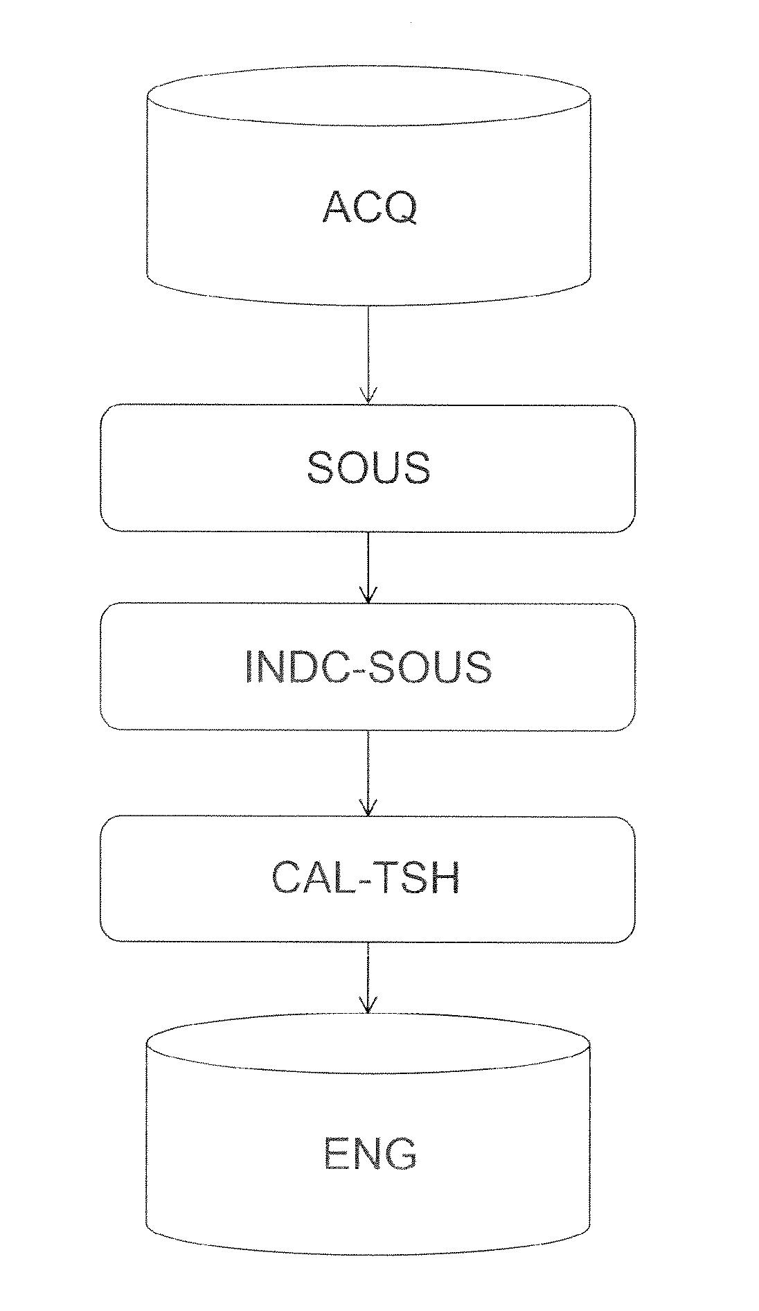
  • Method, system and computer program for learning phase of an acoustic or vibratory analysis of a machine
  • Method, system and computer program for learning phase of an acoustic or vibratory analysis of a machine
  • Method, system and computer program for learning phase of an acoustic or vibratory analysis of a machine

Examples


Embodiment Construction

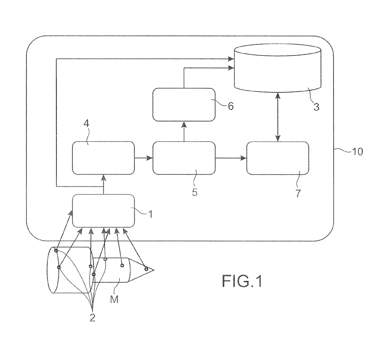
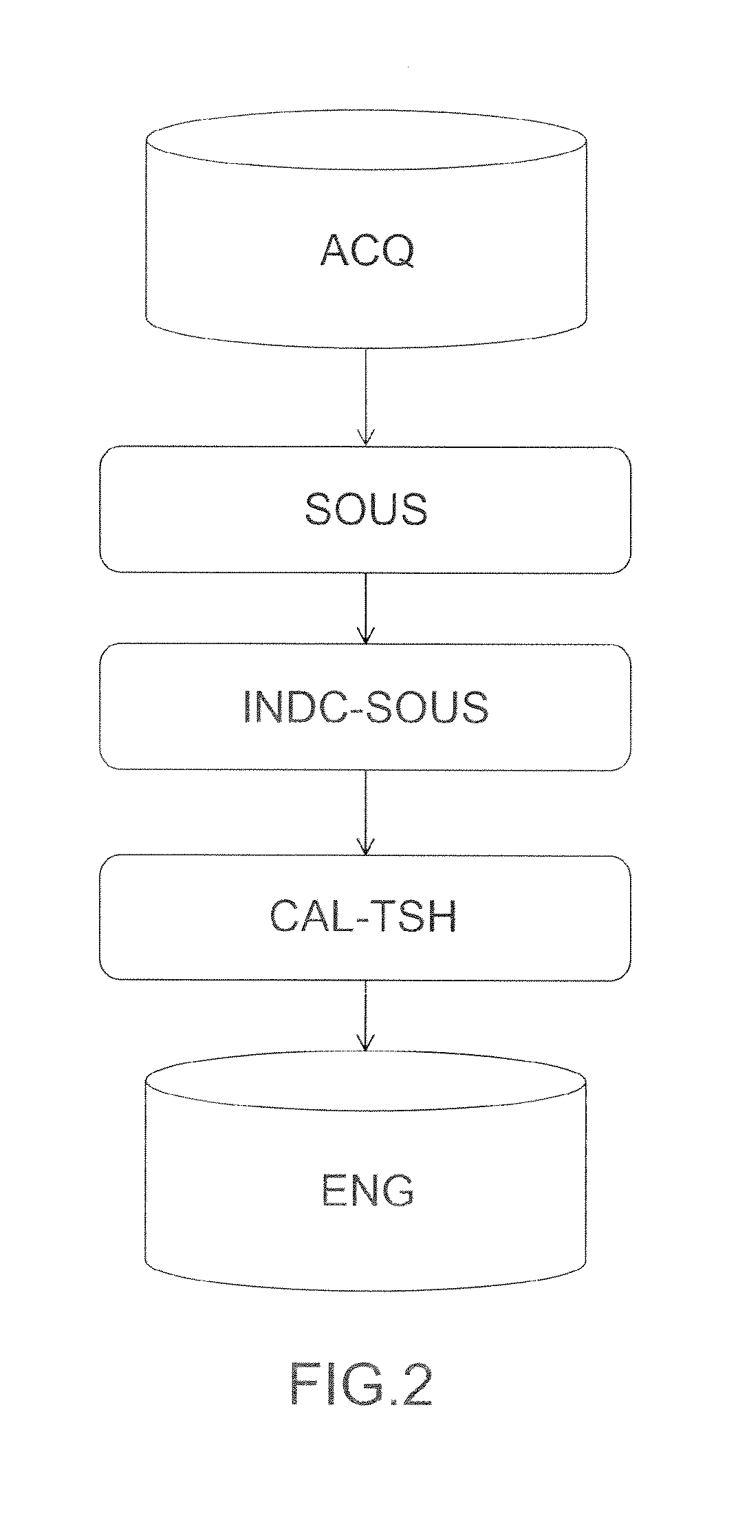
[0009]The aim of the invention is to respond to this set of problems. To do this it proposes a method of analysis of the operational state of a machine, such as an aircraft engine, comprising a learning step to provide data, to a reference database, on one or more thresholds for one or more indicators calculated from signals provided by one or more sensors associated with the machine, characterised in that the learning step comprises the following operations, implemented by a computerised processing unit:[0010]acquisition of signals characteristic of normal operation of the machine and of signals characteristic of abnormal operation of the machine;[0011]for each of the signals characteristic of normal operation, the calculation of at least one so-called deviation signal through the use of a mathematical operation whose attributes are the signal characteristic of normal operation and one of the signals characteristic of normal or abnormal operation other than said signal characterist...


PUM


Abstract

A method of analysis of the state of operation of a machine including a learning step supplementing a reference database with one or more thresholds for one or more indicators calculated on the basis of signals delivered by a sensor associated with the machine, the learning step including the following operations implemented by a computer processing unit; an acquisition of signals characteristic of normal operation and of abnormal operation of the machine: of each of the signals characteristic of normal operation, formation of at least one so-called deviation signal by implementing a mathematical operation having as attributes the signal characteristic of normal operation and one of the signals characteristic of normal or abnormal operation other than the signal characteristic of the normal operation; for each of the deviation signals, calculation of an indicator; determination of an indicator threshold representative of a limit between normal operation and abnormal operation of the machine.

Description

TECHNICAL FIELD[0001]The invention relates to the field of monitoring of a machine, for example an engine such as an aircraft engine. In particular the invention relates to a method and a system for analysis of a machine, for example acoustic or vibratory analysis, in order to detect, recognise or foresee anomalies in it.STATE OF THE PRIOR ART[0002]A machine is a mechanical system which is subject to stresses which may cause wear in its components. A general method of monitoring the state of a machine as effectively as possible is therefore sought, in order to detect any damage to it, to recognise these types of damage from a set of possible types of damage for the machine or to predict their occurrence.[0003]Although a machine, for example an aircraft engine, exhibits the drawback of generating noise, it may be imagined however that this drawback could be used to perform a diagnosis or prognosis of damage in a non-intrusive manner. Indeed, aircraft engines and rotating machines in ...

Claims


Application Information

Patent Timeline
Patent Type & Authority Applications(United States)
IPC IPC(8): G05B23/02F02D41/22G01M15/14G07C3/00G01M13/00
CPCG05B23/0235G01M15/14F02D41/22G07C3/00F02D2200/025G06F11/3452G05B23/02G06F11/34G01H17/00
Inventor BENSE, WILLIAMBOITEUX, JEAN-MICHELDUPONT, AUDREYGRIFFATON, JULIEN CHRISTIAN PASCALLACAILLE, JEROME HENRI NOEL
Owner SN DETUDE & DE CONSTR DE MOTEURS DAVIATION S N E C M A
Learn More