
Oven controlled MEMS oscillator

Active Publication Date: 2018-01-18
MURATA MFG CO LTD
View PDF3 Cites 5 Cited by
  • Summary
  • Abstract
  • Description
  • Claims
  • Application Information

AI Technical Summary

Benefits of technology

The patent discusses a new device that can accurately control the timing of electronic signals. The device uses a small mechanical structure called a MEMS resonator that vibrates at high frequencies, and can be heated very quickly with low power. The invention solves the limitations of existing devices, which use bulky and power-hungry components. The device includes a rectangular frame, support beams, a resonator, a thermistor, and a heater. The resonator is held within a cavity of the frame and is thermally isolated from the frame. The device can be used in various electronic devices, such as timing devices and communication equipment.

Problems solved by technology

Moreover, changes in temperature causes the quartz crystal to expand or contract due to thermal expansion and changes in the elastic modulus of quartz.
Although quartz has a very low temperature coefficient of frequency, temperature changes are still the major cause of frequency variation in crystal oscillators.
Since other electronic components in the oscillator circuit are also vulnerable to temperature drift, usually the entire oscillator circuit is enclosed in the oven.
Moreover, the frequency of the device will not have the full rated stability during this warm-up period.
First, a typical quartz crystal is fairly large, which, turn, makes the final OCXO devices quite large.
Second, the long thermal time constant for heating and cooling leads to a very long start-up time.
For example, it typically takes several minutes to stabilize the oven at the target temperature.
Third, the power needed to maintain the oven temperature is fairly large.

Method used


Image

  • Oven controlled MEMS oscillator
  • Oven controlled MEMS oscillator
  • Oven controlled MEMS oscillator

Examples


Embodiment Construction

[0022]Example aspects are described herein in the context of an oven controlled micromechanical oscillator (hereinafter “OCMO”) that overcomes many of the technical disadvantages of existing oscillator devices. In particular, the OCMO disclosed herein is small-sized oscillator that can be heated very rapidly with very low power.

[0023]Those of ordinary skill in the art will realize that the following description is illustrative only and is not intended to be in any way limiting. Other aspects will readily suggest themselves to those skilled in the art having the benefit of this disclosure. Reference will now be made in detail to implementations of the example aspects as illustrated in the accompanying drawings. The same reference indicators will be used to the extent possible throughout the drawings and the following description to refer to the same or like items.

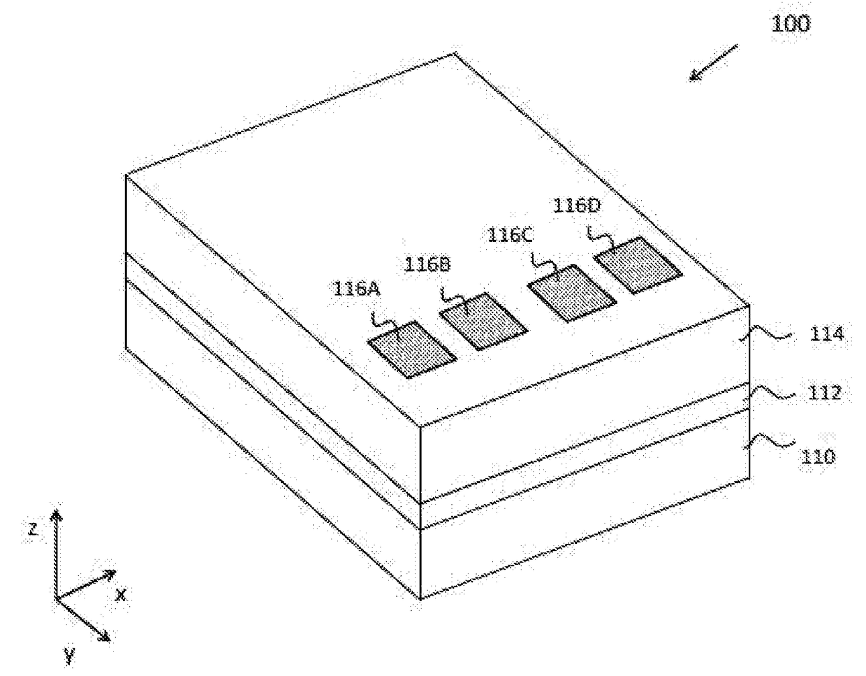
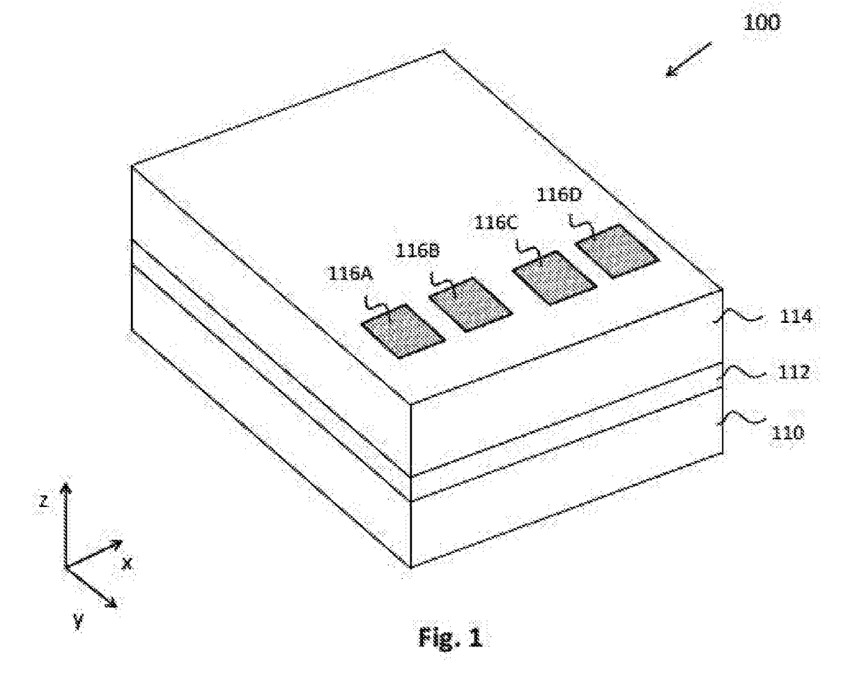
[0024]FIG. 1 illustrates an outer perspective view of an oven controlled micromechanical resonator in accordance with an e...


PUM


Abstract

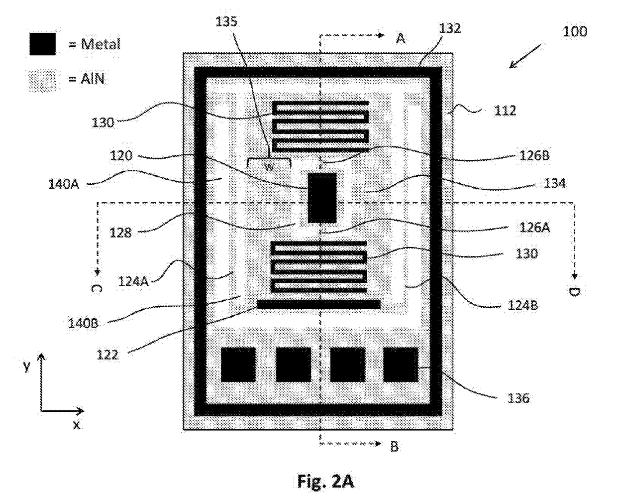
An oven controlled MEMS timing device that includes a very small oscillator that can be heated very rapidly with very low power. The MEMS device includes a rectangular frame, a heated platform positing in the frame, and a pair of support beams that extend from the rectangular frame and hold the platform within a cavity of the frame to thermally isolate the platform. Moreover, the device includes a resonator attached to the platform by a pair of anchor beams, a heater that heats the platform to maintain a target temperature for the resonator and a thermistor that measures a temperature of the platform to provide a control loop for the heater.

Description

FIELD OF THE INVENTION[0001]The present invention relates to a MEMS oscillator, and, more particularly, to an oven controlled MEMS oscillator with good temperature stability in a small size.BACKGROUND OF THE INVENTION[0002]Quartz crystals are widely used to provide reference frequencies in electronic oscillators. The frequency at which a quartz crystal resonator vibrates depends on its physical dimensions. Moreover, changes in temperature causes the quartz crystal to expand or contract due to thermal expansion and changes in the elastic modulus of quartz. The physical changes in turn change the crystal oscillation frequency. Although quartz has a very low temperature coefficient of frequency, temperature changes are still the major cause of frequency variation in crystal oscillators.[0003]Oven controlled crystal oscillators (“OCXO”) are frequency reference devices where the quartz oscillator is placed inside a temperature controlled oven. The oven is provided to maintain the oscilla...

Claims


Application Information

Patent Timeline
IPC IPC(8): H03L1/04H03L1/02H03H9/02
CPCH03L1/04H03L1/028H03H9/02102H03H9/08H03B5/30H03H9/02H03H9/02448
Inventor KAAJAKARI, VILLE
Owner MURATA MFG CO LTD
Learn More