
Particle burner including a catalyst booster for exhaust systems

Inactive Publication Date: 2007-10-18
PURIFY SOLUTIONS INC
View PDF69 Cites 1 Cited by
  • Summary
  • Abstract
  • Description
  • Claims
  • Application Information

AI Technical Summary

Benefits of technology

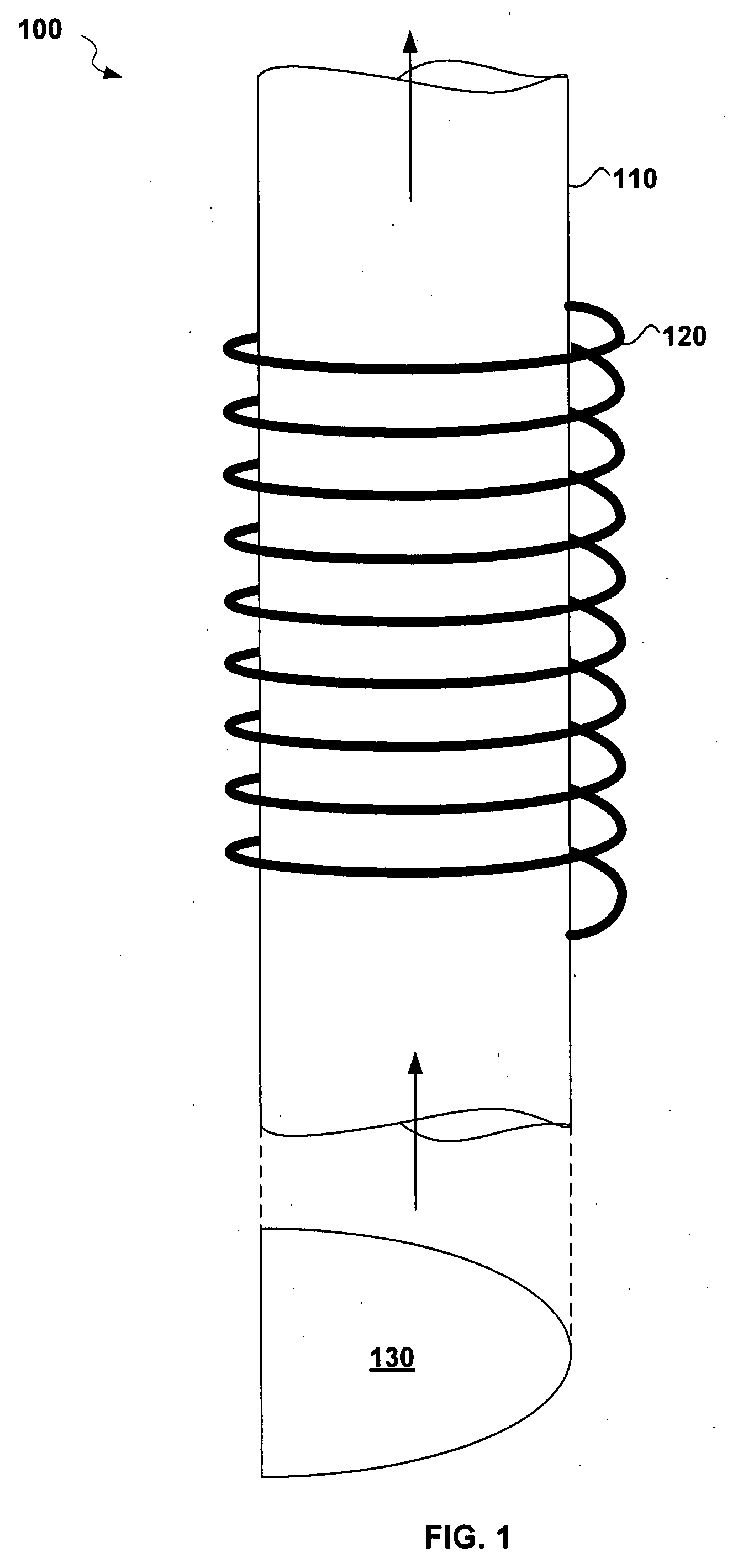
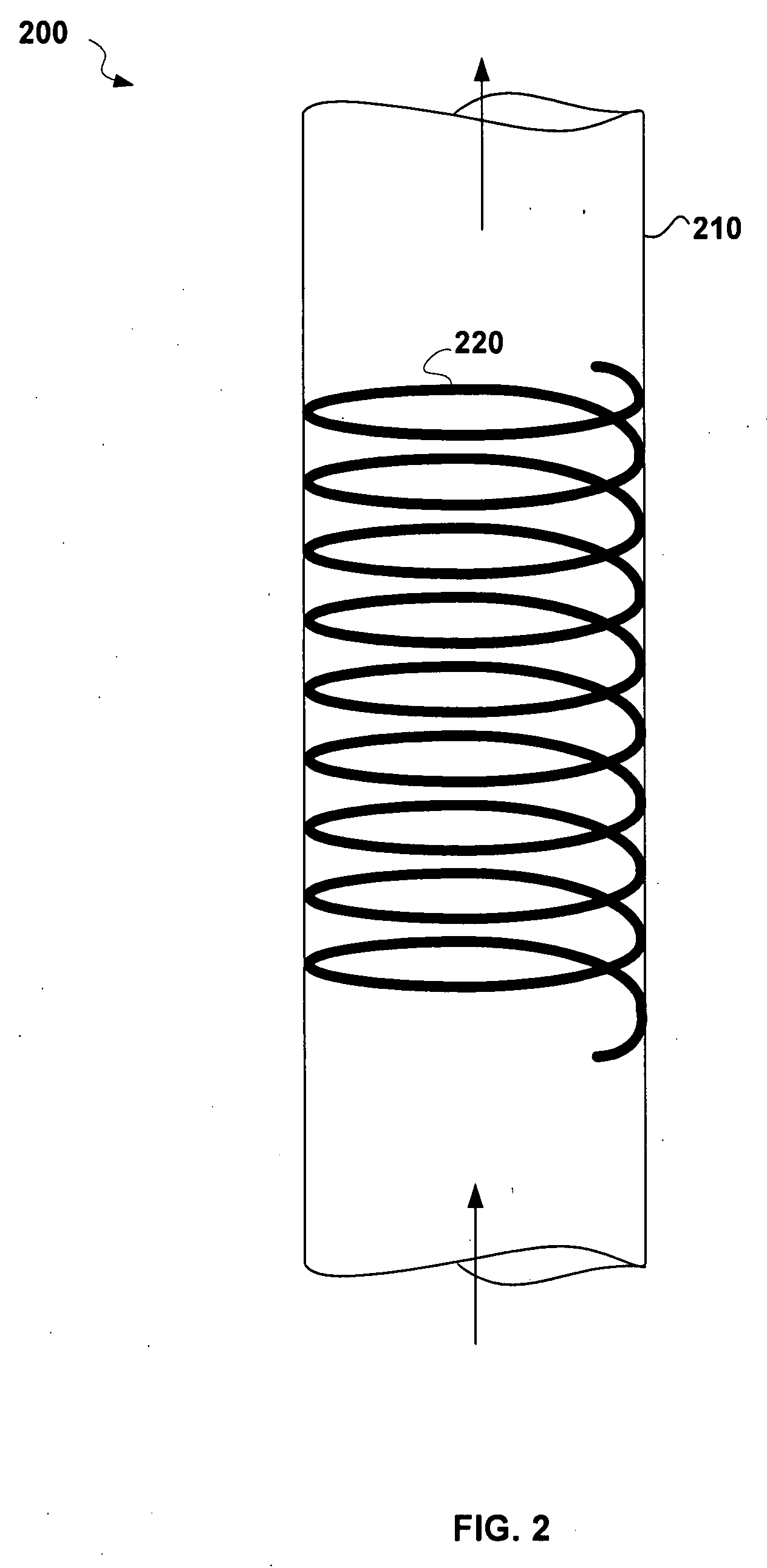
[0011]Particles in an exhaust stream passing through the combustion chamber are heated by the radiation to an ignition point and are consequently removed from the exhaust by burning. Microwave radiation tuned to excite a molecular bond found in the particles can be particularly effective for heating the particles rapidly. Additional air or fuel can be added to the combustion chamber, as needed, to promote better combustion. Once a flame front is established in the combustion chamber, the combustion reaction can become self-sustaining so that further radiation from the radiation source is no longer required.
[0012]In some embodiments, the combustion chamber has a non-circular cross-section perpendicular to a longitudinal axis of the chamber. In some of these embodiments, the cross-section is at least partially parabolic to focus heat from the burning particles back into a hot zone within the combustion chamber where the particle burning preferentially occurs. The combustion chamber can be thermally insulated to better retain heat in order to maintain the combustion reaction. The exhaust system can also comprise a thermally insulated exhaust pipe leading to the combustion chamber to further reduce the loss of heat from the exhaust stream before particle burning can occur. In some embodiments, a reverse flow heat exchanger is placed in fluid communication with the combustion chamber so that heat is transferred to the incoming exhaust stream from the combusted exhaust stream exiting the combustion chamber. In certain embodiments, the reverse flow heat exchanger is also thermally insulated.
[0013]One advantage of certain embodiments of the present invention is the absence of a particle filter or trap within the combustion chamber. While prior art systems have attempted to trap particles and then periodically clean the trap or filter, these systems create significant back-pressure as such traps and filters obstruct the exhaust flow, especially as they become plugged with particles. Continuously burning the particles in the combustion chamber without the use of such traps or filters provides a more simple design that additionally reduces back-pressure.
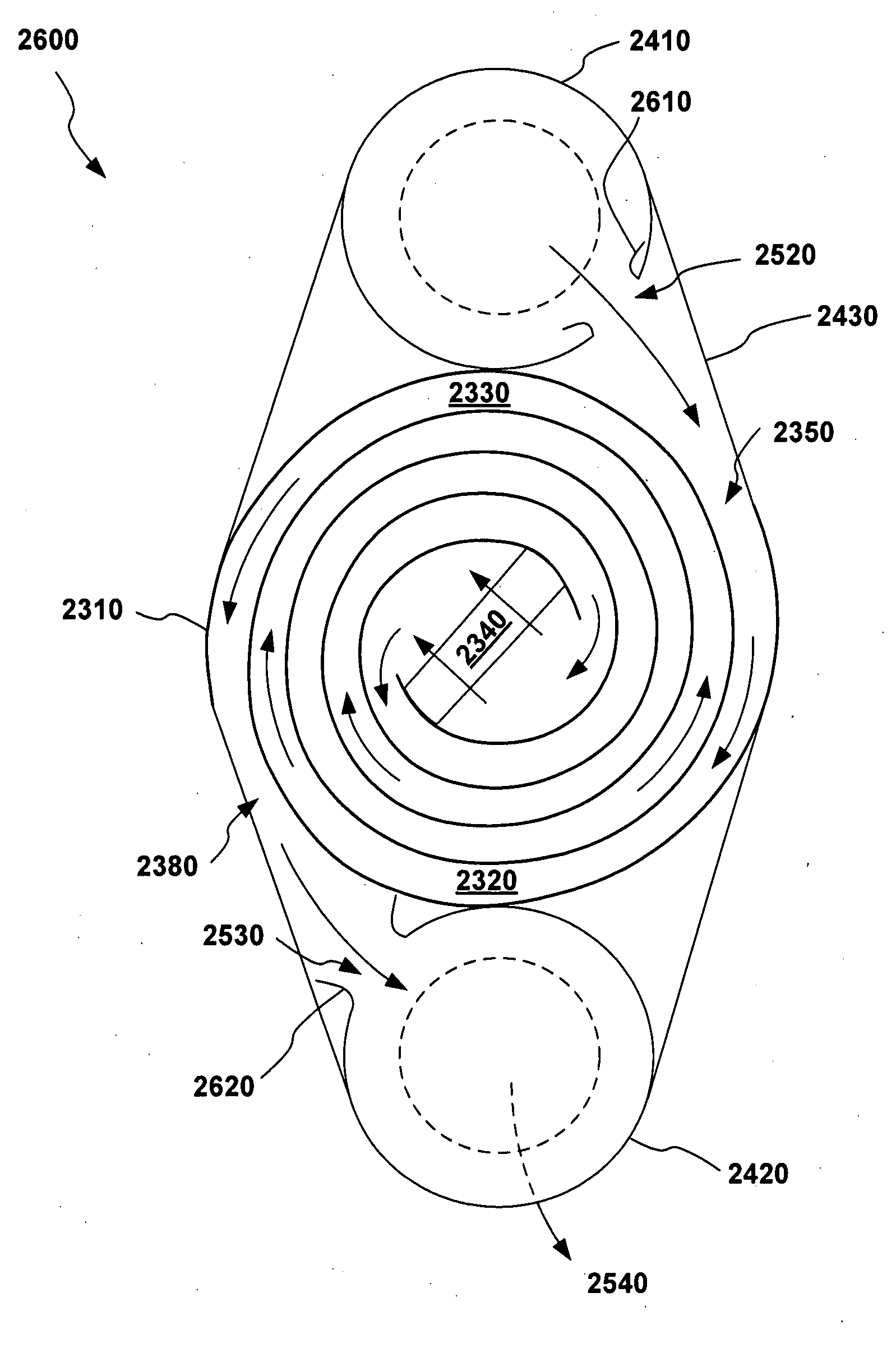
[0019]An exhaust system comprises a reverse flow heat exchanger including a plate defining a plane and separating an exit chamber and an intake chamber. Each chamber of the heat exchanger has an inlet and an outlet located at opposing ends to allow flow therethrough. The exhaust system also comprises a first manifold coupled to the reverse flow heat exchanger and in fluid communication with the intake chamber inlet. A vane disposed within the first manifold is situated relative to the intake chamber inlet so as to reduce resistance to fluid flow near the intake chamber inlet. The exhaust system can also comprise a heating manifold that receives exhaust from the intake chamber, heats the exhaust, and returns the exhaust to the exit chamber. In some embodiments, the heating manifold is a combustion chamber for burning particles in the exhaust. In these embodiments the exhaust system can also comprise a radiation source for heating the particles to at least an ignition temperature.
[0020]Another exemplary exhaust system comprises a first manifold and a reverse flow heat exchanger coupled to the first manifold. Here, the reverse flow heat exchanger defines a transverse plane and includes a plurality of parallel plates separating a number of chambers, each chamber having an inlet and an outlet. These chambers comprise a set of intake chambers alternating with a set of exit chambers, where the inlets of the intake chambers being in fluid communication with the first manifold and the outlets of the intake chambers being in fluid communication with the inlets of the exit chambers. The exhaust system can further comprise a heating manifold coupled to the reverse flow heat exchanger to provide the fluid communication between the outlets of the intake chambers and the inlets of the exit chambers.

Problems solved by technology

While prior art systems have attempted to trap particles and then periodically clean the trap or filter, these systems create significant back-pressure as such traps and filters obstruct the exhaust flow, especially as they become plugged with particles.

Method used


Image

  • Particle burner including a catalyst booster for exhaust systems
  • Particle burner including a catalyst booster for exhaust systems
  • Particle burner including a catalyst booster for exhaust systems

Examples


Embodiment Construction

[0045]An exhaust system comprises a combustion chamber and a radiation source to facilitate the combustion of particles within the chamber. Once ignited, the combustion can continue so long as the concentration of particles in the exhaust entering the chamber remains sufficiently high. The disclosed device can replace both the muffler and the catalytic converter in a vehicle exhaust system and offers reduced back pressure for better fuel economy and lower maintenance costs. The device requires little to no maintenance and is self-cleaning.

[0046]FIG. 1 depicts an exhaust system 100 comprising a combustion chamber 110 and a radiation source 120. The combustion chamber 110 can be constructed using any suitable material capable of withstanding the exhaust gases at the combustion temperature of the particles. Suitable materials include stainless steel, titanium, and ceramics. In one embodiment, the combustion chamber 110 has a non-circular cross-section 130 perpendicular to a longitudina...


PUM


Abstract

An exemplary exhaust cleaner comprises a reverse flow heat exchanger and a gas permeable catalyst. The reverse flow heat exchanger includes two interleaved ducts that are spiral-wound around a central volume. The gas permeable catalyst is disposed within the central volume and separates the central volume into first and second regions. The first duct of the reverse flow heat exchanger opens into the first region, and the second duct opens into the second region. The heat generated at the catalyst by the catalysis of incomplete combustion products within the exhaust heats the exhaust within the central volume to a temperature sufficient to burn particulates within the exhaust. The heat generated within the central volume by the catalysis and the combustion of any particulates is carried by the exhaust into the second duct where the heat is transferred to the cooler exhaust within the first duct.

Description

CROSS-REFERENCE TO RELATED APPLICATIONS[0001]This application is a continuation-in-part of U.S. patent application Ser. No. 11 / 404,424 filed Apr. 14, 2006 and titled “Particle Burning in an Exhaust System,” a continuation-in-part of U.S. patent application Ser. No. 11 / 412,289 filed Apr. 26, 2006 and titled “Air Purification System Employing Particle Burning,” and a continuation-in-part of U.S. patent application Ser. No. 11 / 412,481 filed Apr. 26, 2006 and titled “Reverse Flow Heat Exchanger for Exhaust Systems.” The disclosures of all of the above U.S. patent applications are hereby incorporated herein by reference.BACKGROUND OF THE INVENTION[0002]1. Field of the Invention[0003]This invention relates generally to exhaust systems and more particularly to systems for cleaning exhaust air.[0004]2. Description of the Prior Art[0005]When a fuel burns incompletely, pollutants such as particles and hydrocarbons are released into the atmosphere. The United States Environmental Protection Ag...

Claims


Application Information

Patent Timeline
IPC IPC(8): F01N3/10
CPCF01N3/023Y02T10/26F01N2240/02F01N3/2006Y02T10/12
Inventor EVANS-BEAUCHAMP, LINCOLN
Owner PURIFY SOLUTIONS INC
Learn More