
Easy load trimmer head spool with non-radial guide channel

a technology of radial guide channel and trimmer head, which is applied in the direction of mowers, agriculture tools and machines, and mowers, etc., can solve the problems of limiting the type of trimmer machine with which such a spool may be engaged, and the spool with a straight radial passageway cannot be used on the trimmer machine with a short drive shaft, so as to achieve cost savings

Inactive Publication Date: 2018-01-25
FIRST TO INVENT LLC
View PDF0 Cites 15 Cited by
  • Summary
  • Abstract
  • Description
  • Claims
  • Application Information

AI Technical Summary

Benefits of technology

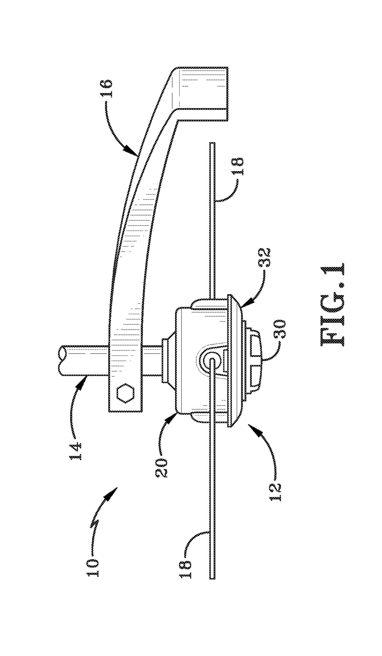
The patent describes a spool for a trimmer machine that has a non-radial guide channel, which is a guide channel that does not align along a radius of the hub. This non-radial guide channel can be used with different types of trimmer heads and can help to keep the trimmer line in a fixed position on the spool. The non-radial guide channel can also increase the friction applied to the line, which can be beneficial in positioning equal lengths of trimmer line between the guide channel openings. The use of a spool with a non-radial guide channel can save manufacturers time and money as they can use the same trimmer head or spool on different machines without needing to make dedicated trimmer heads for each machine. The non-radial guide channel can be straight or non-linear, with the non-linear shape designed to minimize force against the trimmer line and prevent it from moving out of position prior to winding into the spool.

Problems solved by technology

This was an extremely problematic and difficult task.
The problem with using a straight, radial passageway may be that this limits the type of trimmer machine with which such a spool may be engaged.
As a result, trimmer head spools that have a straight radial passageway can only be used on trimmer machines that have short driveshafts.
Utilizing a spool with a straight radial passageway on a trimmer machine that has a long driveshaft designed to pass through the center of the spool may be therefore not possible.
As a result, this spool cannot be engaged with long driveshaft trimmer machines as the long driveshaft pass through the axis of the spool.

Method used


Image

  • Easy load trimmer head spool with non-radial guide channel
  • Easy load trimmer head spool with non-radial guide channel
  • Easy load trimmer head spool with non-radial guide channel

Examples


first embodiment

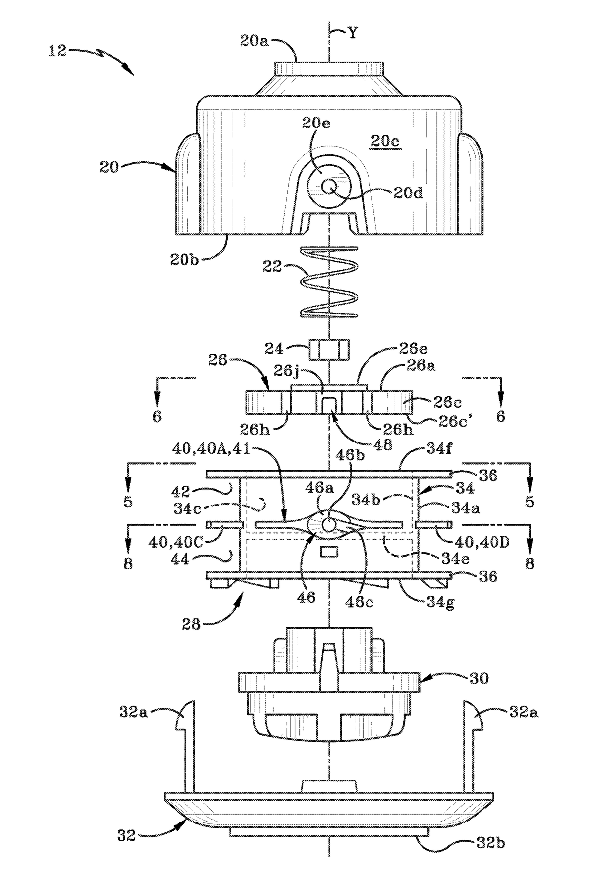
[0107]a guide channel module 26 in accordance with the present disclosure may be shown in FIGS. 3-6. Module 26 may be a disc-like object that has a first end 26a, a second end 26b, and a peripheral wall 26c. Peripheral wall 26c originates at first end 26a and extends for a distance outwardly beyond second end 26b. This can be seen in FIG. 4. Second end 26b may therefore be recessed relative to an outermost end 26c′ of peripheral wall 26c. Guide channel module 26 does not include any central opening in first and second ends 26a, 26b through which a region of driveshaft 14 might pass when guide channel module 26 may be received in bore 34c of spool 28. When guide channel module 26 may be engaged with spool 28, outermost end 26c′ of guide channel module 26 rests on wall 34e of spool 28. Guide channel module 26 and wall 34e therefore effectively block bore 34c of spool 28. When module 26 may be placed on wall 34e, the guide channel 48 defined by module 26 aligns with funnels 46 in inter...

second embodiment

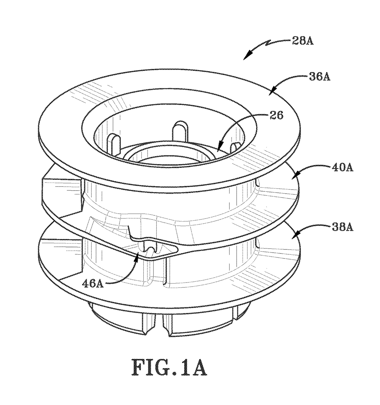
[0117]FIGS. 10A and 10B show a spool, generally indicated at 128. Spool 128 may include a cylindrical hub 134 that has a first flange 136 at a top end and a second flange 138 at a bottom end. An exterior surface 134a of hub, first flange 136 and second flange 138 bound and define a single storage compartment 143. Hub 134 has an interior surface 134b that bounds and defines a bore 134c. A wall 134d extends across bore 134c or, alternatively one or more projections extend into bore 134c from interior surface 134b. A module 126 (shown in detail in FIGS. 11A, 11b) may be engaged with spool 128 such that module 126 sits on wall 134d or on projections extending into bore 134c. Module 126 may be therefore engaged with spool and provides a way for trimmer line (18) to be routed across the bore 134c of spool 128.

[0118]Flange 136, unlike flange 40, comprises an annular ring that extends radially outwardly from exterior surface 134a of wall 134. Flange 136, like flange 40 defines a funnel open...

third embodiment

[0130]FIG. 13 shows that spool 228 may be provided with a trimmer line conduit 250 that may be integrally formed with intermediate flange 240. Trimmer line conduit 250 may be comprised of a guide channel 248 and two funnel openings 246. Guide channel 248 may be integrally formed with hub 234 and extends from one part of the interior surface 234b of hub 234 to another part of the interior surface 234b. At least a portion of guide channel 248 spans bore 234c. Guide channel 248 may be a non-radial guide channel. In other words, guide channel 248 does not pass through a center point “Y” of spool 228 but instead bypasses, goes around and may be offset from the center point “Y”. (Spool 228 may be rotatable about the axis “Y” that passes through the center point.)

[0131]Guide channel 248 may be defined by at least two spaced apart upstanding walls 248a, 248b, and a horizontal wall 248c. Walls 248a, 248b, 248c may be integrally formed with a region of intermediate flange 240 that spans bore ...


PUM

PropertyMeasurementUnit
Lengthaaaaaaaaaa
Angleaaaaaaaaaa
Distanceaaaaaaaaaa

Abstract

A trimmer head spool for a vegetation trimmer machine. The spool includes a hub that defines a bore and has at least one flange or a plurality of spokes extending radially outwardly therefrom. A trimmer line conduit defined in the spool includes a first funnel defined in a first region of the flange or spokes and a second funnel defined in a second region of the flange or spokes. A non-radial guide channel is in fluid communication with the first and second funnels. The non-radial guide channel spans the hub's bore and does not extend through a central axis of the spool about which the spool is rotatable. The non-radial guide channel may be provided on a module that is selectively inserted into the bore and aligned with the first and second funnels. In other embodiments the entire trimmer line conduit is integrally formed in the spool.

Description

CROSS REFERENCE TO RELATED APPLICATIONS[0001]This application is a Continuation-in-Part of U.S. application Ser. No. 15 / 376,474 filed Dec. 12, 2016, which is a Continuation-in-Part of U.S. patent application Ser. No. 14 / 548,392 filed Nov. 20, 2014, now U.S. Pat. No. 9,516,807, which claims the benefit of U.S. Provisional Application No. 61 / 907,883 filed Nov. 22, 2013.[0002]U.S. patent application Ser. No. 14 / 548,392 filed Nov. 20, 2014, now U.S. Pat. No. 9,516,807, is also a Continuation-in-Part of U.S. patent application Ser. No. 12 / 428,453 filed Apr. 22, 2009, now U.S. Pat. No. 8,910,387 which claims the benefit of U.S. Provisional Application No. 61 / 071,321, filed Apr. 22, 2008.[0003]The present application also claims the benefit of U.S. Provisional Application No. 62 / 397,313 filed Sep. 20, 2016.[0004]The disclosures of each of the above U.S. applications are incorporated herein by reference.BACKGROUNDTechnical Field[0005]This disclosure relates generally to line type vegetation...

Claims


Application Information

Patent Timeline
IPC IPC(8): A01D34/416
CPCA01D34/4163Y10T29/49826Y10T29/49838
Inventor ALLISS, GEORGE E.
Owner FIRST TO INVENT LLC
Learn More