

Sensor attachment structure
a technology of sensor and attachment structure, which is applied in the direction of instruments, liquid fuel engines, machines/engines, etc., can solve the problems of oil pressure sensor b>3/b> becoming damaged, and the workability is very low
- Summary
- Abstract
- Description
- Claims
- Application Information
AI Technical Summary
Benefits of technology
Problems solved by technology
Method used
Image

Examples
first embodiment
1. First Embodiment
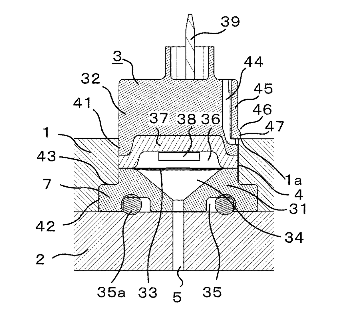
[0031]Referring to FIGS. 1 and 2, a first embodiment of the present invention will be described.
[0032]A valve body includes an upper body 1 and a lower body 2. The upper body 1 has an accommodation space 4 in which an oil pressure sensor 3 is to be placed. An oil passage 5 extends upward through the lower body 2 toward the upper body 1. The oil pressure sensor 3 is fixed at an opening of the oil passage 5.
[0033]A casing of the oil pressure sensor 3 is inserted upward into the accommodation space 4 along the central axis. The accommodation space 4 is a through-hole extending through the upper body 1 from an upper surface to a lower surface of the upper body 1. An upper edge of the through-hole, which is the accommodation space 4, at the upper surface of the upper body 1 is a stopper la that prevents downward movement of an engagement portion 47 along the central axis of the oil pressure sensor 3.
[0034]The accommodation space 4 includes a small-diameter portion 41 i...
second embodiment
2. Second Embodiment
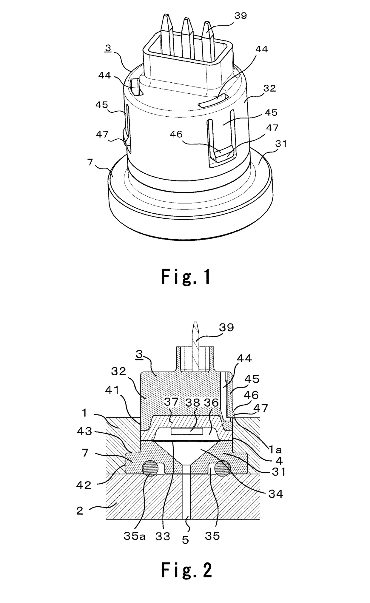
[0053]Referring to FIGS. 3 and 4, a second embodiment of the present invention will be described. Elements of the second embodiment that are the same as those of the first embodiment will be denoted by the same numerals and descriptions of such elements will be omitted.
[0054]In the second embodiment, an annular recess 44 that extends in the circumferential direction is formed along the entire outer peripheral surface of an upper case 32. Three elastic members 45 are disposed at regular intervals so as to bridge the annular recess 44 in the up-down direction along the central axis. Upper and lower ends of the elastic members 45 are fixed to the surface of the upper case 32. Each of the elastic members 45 is made of an appropriate material and has an appropriate thickness such that a central part of the elastic member 45 in the up-down direction along the central axis can elastically deform so that the central part moves toward and away from the central axis. An en...
third embodiment
3. Third Embodiment
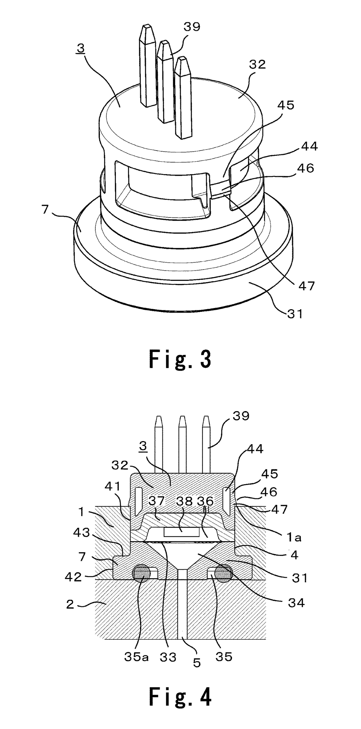
[0056]Referring to FIGS. 5 and 6, a third embodiment of the present invention will be described. Elements of the third embodiment that are the same as those of the first embodiment will be denoted by the same numerals and descriptions of such elements will be omitted.
[0057]In the third embodiment, a stopper 1a of an upper body 1 is a protrusion that protrudes toward the central axis of an oil pressure sensor 3 from an upper edge portion of a through-hole that is an accommodation space 4. Elastic members 45, whose lower ends are fixed to the upper case 32, are formed in the upper case 32. A recess that is recessed toward the central axis is formed in an outer peripheral surface of each of the elastic members 45, and the recess is an engagement portion 47.
[0058]An inclined surface 46 is formed in each of an outer peripheral surface of an upper part of the elastic member 45, a lower part of the engagement portion 47, and a lower part of the stopper 1a. The inclined s...
PUM
 Abstract
Description
Claims
Application Information