Modular flotation system

a flotation system and modular technology, applied in underwater equipment, special-purpose vessels, transportation and packaging, etc., can solve the problems of not always desirable or cost-effective permanent installation of flotation on equipment, and the flotation arrangement for one mission may not be apt for another mission, so as to facilitate temporary installation of modular flotation arrangement

Active Publication Date: 2018-02-01
CONTINENTAL SHELF ASSOC
View PDF1 Cites 6 Cited by
  • Summary
  • Abstract
  • Description
  • Claims
  • Application Information

AI Technical Summary

Benefits of technology

[0012]It is an aspect of the present disclosure to facilitate temporary installation of modular flotation arrangements that are useful for deployment and positioning of equipment on the seafloor, especially using Remotely Operated Vehicles (ROVs). Among other objects, the modular flotation arrangements are configurable to supply different amounts of buoyancy for successive missions characterized by different payload size and weight conditions. The modular flotation arrangements also are adaptable to accommodate missions that traverse different and possibly substantial depths.
[0013]The mounting arrangements advantageously are arranged so that standard Remotely Operated Vehicle manipulator tools can be used to remove, untether or detach some or all of the temporary flotation modules after use, especially to enable recovery for re-use. Exemplary interfacing elements including release pins and shackles can be provided as disclosed herein, and are advantageous to enable ready engagement and disengagement of the modular flotation assemblies, at least with one another, and also to payloads and ROVs. Once disconnected from a payload, the modular flotation assembly can be returned to the surface and its elements reused in a mission with similar or quite different flotation needs.

Problems solved by technology

A challenge for operators of vehicles and divers or on-board vehicle crew is to maintain a manageable near neutral buoyancy when attempting to move a payload in seawater, so that the vehicle can control the depth and position of the payload during transport and also during manipulation at the subsea work site, without the need for the vehicle to exert a great deal of thrust.
Permanent installation of flotation on the equipment is not always desirable or cost effective.
If the tool package is to be used or to be variably configured from mission to mission, the flotation arrangements for one mission may not be apt for another mission.

Method used


Image

  • Modular flotation system
  • Modular flotation system
  • Modular flotation system

Examples


Embodiment Construction

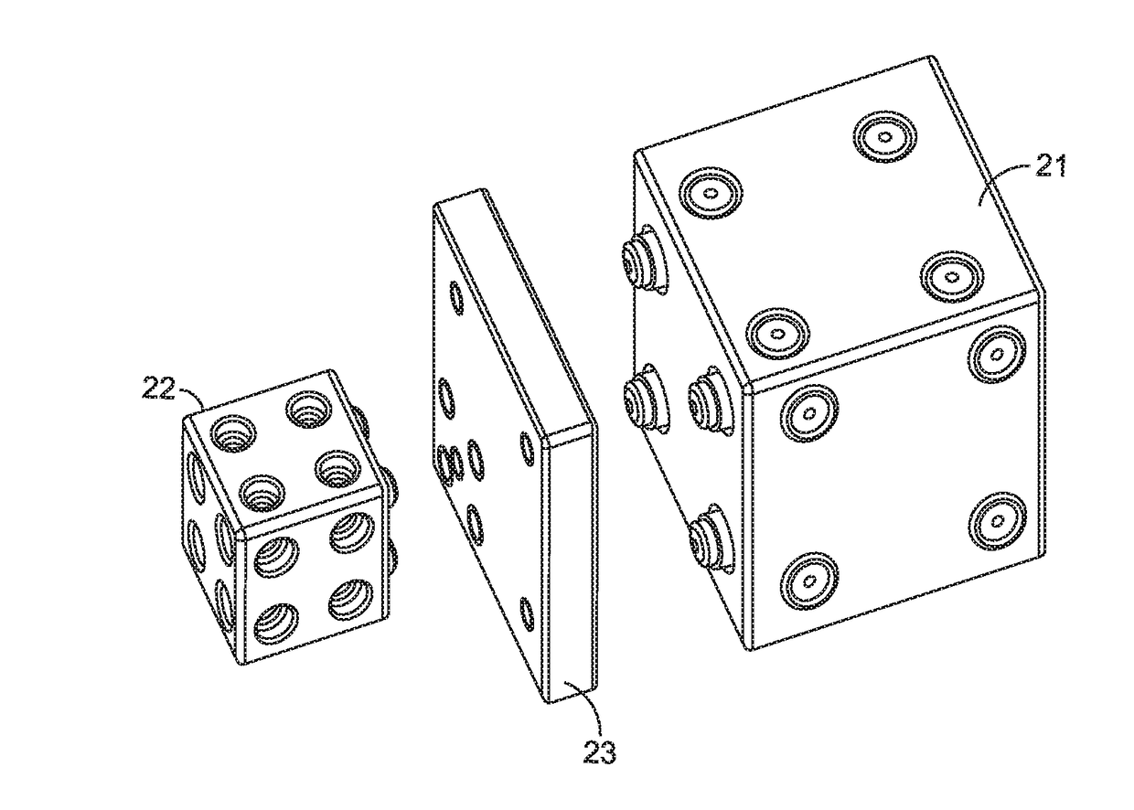
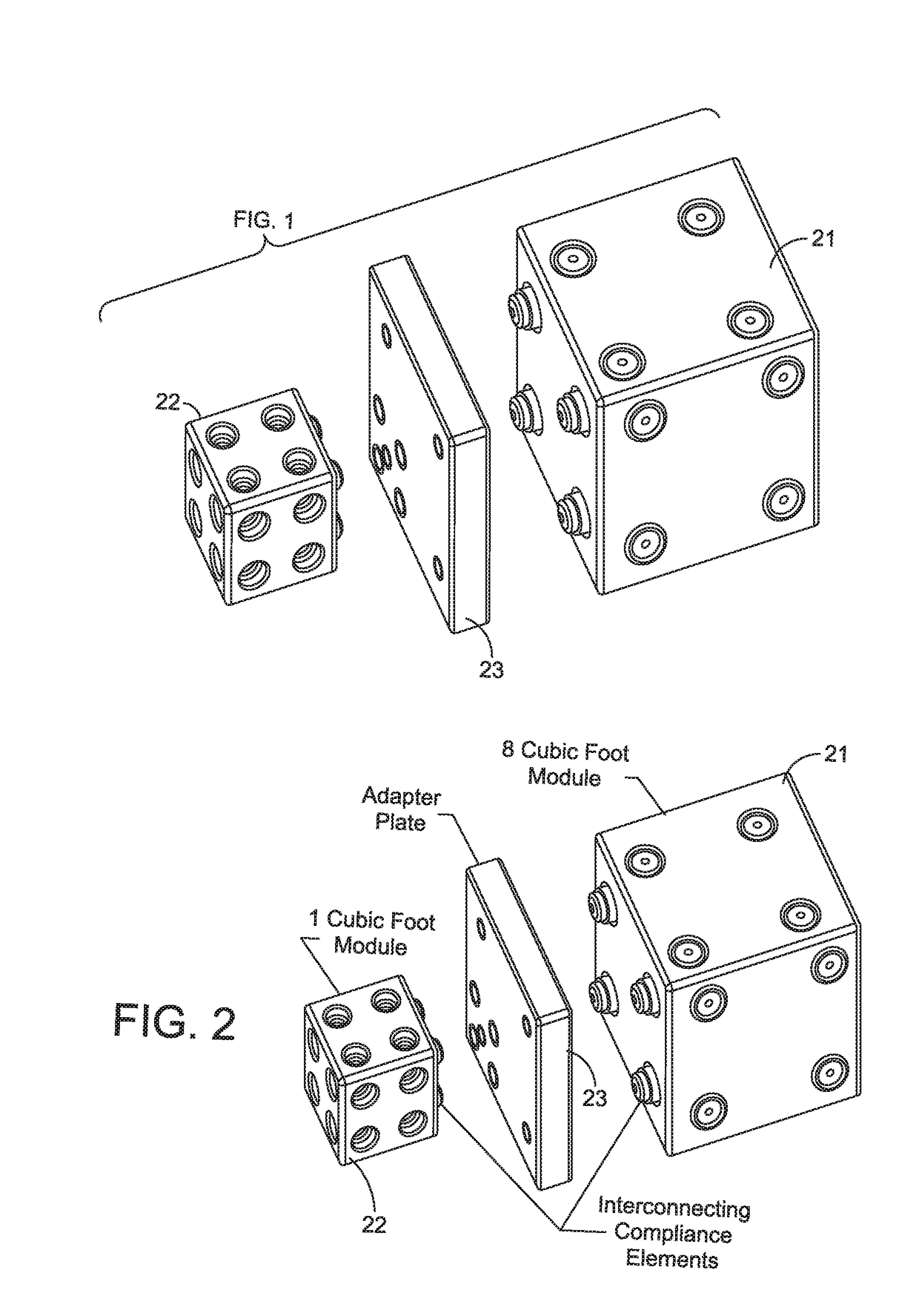
[0029]The invention comprises one or more arrays of two or more interlocking standardized flotation modules 21. The modules can be of equal size, or as shown in FIG. 1, modules 21, 22 of different sizes can be configured to be attachable and detachable directly or indirectly through interface elements 23 to form arrays. For making the structural attachments between modules and to structures that are external to the array such as loads or submersible vehicles, related fixtures and hardware including structural members and components are provided for detachable connection and positioning as described in detail herein. These parts enable a user to create any number of configurations of plural preferably-standardized flotation module arrays, by selecting among modules and attaching the selected modules to one another in a building block manner to form arrays of plural connected modules.

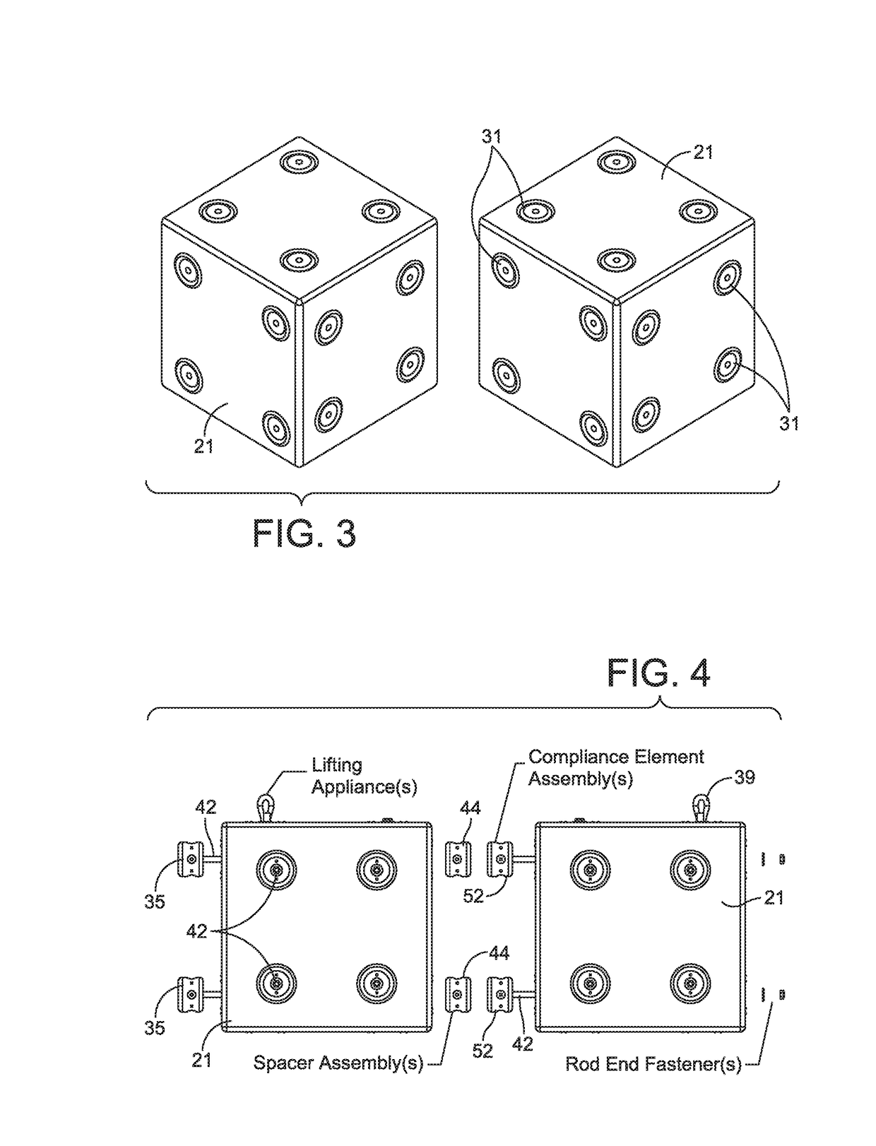
[0030]The arrays of plural modules can be elongated by abutting and attaching modules in one, two or t...


PUM

PropertyMeasurementUnit
sizesaaaaaaaaaa
depthaaaaaaaaaa
depthaaaaaaaaaa

Abstract

A buoyant apparatus and method of use buoyancy to offset the weight of a load during immersion of the load in a fluid medium such as a payload manipulated by a cable and crane or by a remotely operated undersea vehicle. Buoyancy modules that can be of different size and shape have elongated supports that are attachable via complementary connection fixtures at the ends. The attached supports form a skeleton of the array. The connection fixtures are axially resiliently compressible and maintain the buoyancy modules in abutment notwithstanding shrinkage or expansion of the buoyant material due to hydrostatic pressure that increases with depth.

Description

BACKGROUND[0001]A modular re-usable buoyancy and flotation apparatus having conveniently connected buoyancy elements to form buoyant arrays of desired sizes, shapes and depth / pressure ratings is adapted for varied jobs in marine construction, scientific research and other subsea applications. The apparatus includes a skeleton of linear supports traversing buoyant shapes, the supports terminating in inter-element connection fixtures that extend and retract resiliently and can compensate for compression of the buoyant medium at the hydrostatic pressures of different undersea depths.[0002]It is known to attach one or more buoyant elements to weight (a “load”) that is to be manipulated below a water surface, e.g., in the sea. Up-thrust from the buoyant element supports some of the weight of the load. The attached load and buoyant element are a movable structural unit, with at least a reduced need to support the weight of the load by other means. Conversely, a load might be buoyant, in w...

Claims


Application Information

Patent Timeline
Patent Type & Authority Applications(United States)
IPC IPC(8): B63G8/24
CPCB63G8/24B63B2207/02B63B77/00F16L1/24B63B2231/50E21B17/012
Inventor PETERSON, KEVINDUPONT, DAVIDDARLING, DONALD
Owner CONTINENTAL SHELF ASSOC
Why Eureka
Try Eureka