Seal device for turbine, turbine, and thin plate for seal device

Active Publication Date: 2018-02-01
MITSUBISHI POWER LTD
View PDF13 Cites 0 Cited by
  • Summary
  • Abstract
  • Description
  • Claims
  • Application Information

AI Technical Summary

Benefits of technology

[0040]According to at least one embodiment of the present invention, it is possible to form an upward flow flowing from the end portion on the side of the rotor of the thin plate toward the end portion on the side of the stator in the gap between the thin plates, and to form a suitable static-pressure distribution for causing the thin plates to levitate from the outer peripheral surface of the rotor. Thus, it is possible to maintain a non-contact state stably between the rotor and the

Problems solved by technology

Furthermore, besides the effect of the static pressure distribution, the dynamic p

Method used


Image

  • Seal device for turbine, turbine, and thin plate for seal device
  • Seal device for turbine, turbine, and thin plate for seal device
  • Seal device for turbine, turbine, and thin plate for seal device

Examples


Example

[0051]Embodiments of the present invention will now be described in detail with reference to the accompanying drawings. It is intended, however, that unless particularly specified, dimensions, materials, shapes, relative positions and the like of components described in the embodiments shall be interpreted as illustrative only and not intended to limit the scope of the present invention.

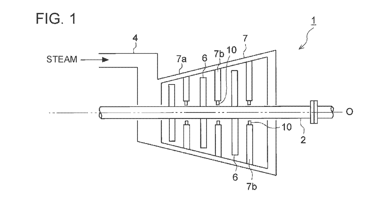
[0052]First, the steam turbine 1 shown in FIG. 1 will be described as an example of a turbine according to the present embodiment. FIG. 1 is a schematic configuration diagram of a steam turbine 1 according to some embodiments.

[0053]As shown in FIG. 1, the steam turbine 1 according to some embodiments is configured to rotary drive the rotor 2 with steam introduced into a casing 7a from a steam inlet 4. In the drawing, the steam discharging mechanism such as an exhaust chamber is not shown.

[0054]Specifically, the steam turbine 1 includes a plurality of rotor blades 6 disposed on the side of the rotor 2...


PUM


Abstract

A seal device for a turbine is disposed around a rotor so as to separate a high-pressure space and a low-pressure space and includes: a plurality of thin plates arranged along an outer peripheral surface of the rotor. Each of the thin plates has a thin-plate tip surface facing the outer peripheral surface of the rotor; a first side plate disposed so as to face the high-pressure space and covering outer peripheral regions of first side surfaces; and a second side plate disposed so as to face the low-pressure space and covering outer peripheral regions of second side surfaces. The first side surface of each of the thin plates is covered with the first side plate in a region extending further to an inner side, in a radial direction of the rotor, than a region of the second side surface covered with the second side plate.

Description

TECHNICAL FIELD[0001]The present disclosure relates to a seal device for a turbine, a turbine, and a thin plate for a seal device.BACKGROUND ART[0002]Generally, in a turbine such as a gas turbine and a steam turbine, a seal device for reducing a leakage amount of a fluid that flows from the high-pressure side toward the low-pressure side is disposed between the outer peripheral surface of a rotor and a stator.[0003]As a type of such seal device, known is a thin-plate seal structure having a plurality of thin plates (leafs) arranged in the circumferential direction of the rotor in a multiple-layered fashion, as disclosed in Patent Documents 1 to 3. The thin plates are normally in contact with the rotor while the turbine is stopped, but the thin-plate tip portions levitate from the rotor peripheral surface while the turbine is in operation, so that the thin plates are mainly in a non-contact state with the rotor. As compared to the labyrinth structure, the thin-plate seal structure is...

Claims


Application Information

Patent Timeline
IPC IPC(8): F01D11/12F16J15/3288
CPCF01D11/12F16J15/3288F05D2220/32F05D2240/56F05D2260/30F16J15/22F16J15/447F05D2240/59F05D2250/182F05D2250/131F01D11/001F16J15/3292F16J15/4472F05D2250/184F05D2250/232F05D2250/13F01D11/02F02C7/28
Inventor YOSHIDA, AZUMIUEHARA, HIDEKAZUOYAMA, HIROHARUOZAKI, KOHEIHAMADA, KATSUHISASUGISHITA, HIDEAKINISHIKAWA, TOYOHARUKUWAMURA, YOSHIHIROHATANO, KOHEIMATSUYAMA, KEISUKE
Owner MITSUBISHI POWER LTD
Why Eureka
Try Eureka