
Method for controlling a power electronics system

Active Publication Date: 2017-10-12
DR ING H C F PORSCHE AG
View PDF1 Cites 2 Cited by
  • Summary
  • Abstract
  • Description
  • Claims
  • Application Information

AI Technical Summary

Benefits of technology

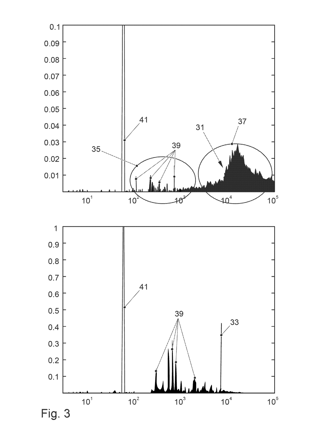
The patent describes a method to reduce the impact of power electronics systems on other electronic devices in a vehicle or user's environment. This is achieved by adapting the spectral characteristics of the power electronics system by selecting a switching state that changes the spectrum of the error signal of the output voltage in a way that reduces the influence of certain frequencies on other devices. This results in a "spectral gap" that minimizes the impact on third-party devices and ensures safe and reliable operation of the power electronics system.

Problems solved by technology

Due to the switching of the power semiconductors, the power electronics system generates an error signal which can interact in its frequency with other electric devices such as, e.g., a radio receiver as a result of which interfering noises or noise effects can be produced.
Particularly in the case of control systems of respective power semiconductors by means of pulse-width modulators, harmonic oscillations frequently occur which act as error signals on other electric devices.

Method used


Image

  • Method for controlling a power electronics system
  • Method for controlling a power electronics system
  • Method for controlling a power electronics system

Examples


Embodiment Construction

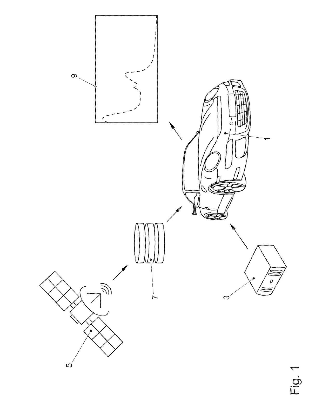
[0057]In FIG. 1, a vehicle 1 is shown which comprises a third-party device in the form of a radio receiver 3 and a power electronics system for controlling an electric motor of the vehicle.

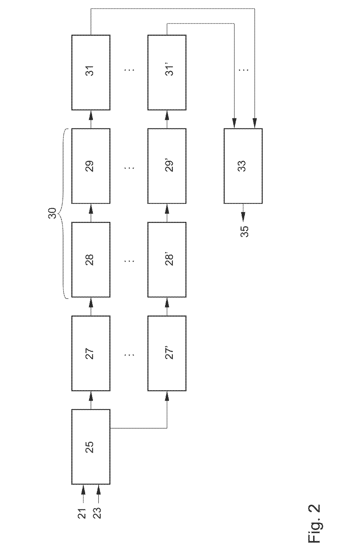
[0058]Since the radio receiver 3 is set in dependence on a current position of the vehicle in order to meet, e.g., national specifications, the current position of vehicle 1 is detected by means of a GPS system 5. By means of the current position of vehicle 1, corresponding national specifications are requested from a database 7 and specifications generated for an error signal of an output voltage of the power electronics system. Depending on the specifications, a target value is generated for a spectrum of the error signal of the output voltage of the power electronics system. This target value or a corresponding target spectrum 9, respectively, is used as initial value for a comparison in which all possible switching states of the power electronics system are simulated and examined for their spe...


PUM


Abstract

Method for controlling a power electronics system for a vehicle in which, while maintaining a current timing of a modulator of the power electronics system, one switching state of the power electronics system from a number of possible switching states of the power electronics system is selected in dependence on at least one requirement, to be provided in advance, for spectral characteristics of an error signal of an output voltage of the power electronics system and is set in the power electronics system.

Description

CROSS-REFERENCE TO RELATED APPLICATIONS[0001]This application claims priority to German Patent Application No. DE 10 2016 106 472.6, filed Apr. 8, 2016, which is incorporated by reference herein in its entirety.FIELD OF THE INVENTION[0002]The present invention relates to a method for controlling a power electronics system for a vehicle and a modulator suitable for performing the method presented.BACKGROUND OF THE INVENTION[0003]When using power electronics for controlling, e.g., electric motors, power semiconductors comprised in a respective power electronics system are switched at a high frequency in order to map various states of the power electronics system. Due to the switching of the power semiconductors, the power electronics system generates an error signal which can interact in its frequency with other electric devices such as, e.g., a radio receiver as a result of which interfering noises or noise effects can be produced. Particularly in the case of control systems of respe...

Claims


Application Information

Patent Timeline
IPC IPC(8): H03K5/04B60R16/03
CPCB60R16/03H03K5/04H02M1/44
Inventor GOTZ, STEFAN
Owner DR ING H C F PORSCHE AG
Learn More