robot

Active Publication Date: 2015-06-04
SEIKO EPSON CORP
View PDF24 Cites 9 Cited by
  • Summary
  • Abstract
  • Description
  • Claims
  • Application Information

AI Technical Summary

Benefits of technology

The patent describes a robot that can detect the movement of the first arm and base, and control the movements of other joints to reduce shaking of the arm. This helps to prevent the arm from oscillating. Additionally, a second sensor on the base can detect any movement of the arm, so that the arm's movements are less affected by the base's movements. This allows for quicker suppression of arm shaking. Overall, this technology helps to create a more stable and efficient robot.

Problems solved by technology

However, when the robot hand or the like is moved to a target position and stopped in order to perform work, the work cannot be started because the distal end of the arm oscillates for a while.
Even if the technique of Patent Literature 1 is applied to this robot, it is difficult to sufficiently suppress the oscillation of an arm.
This is because, when the distal end of the arm is oscillating, for example, since control contents (a control amount and a control direction) concerning a joint on the distal end side of the arm change according to a rotation position of a joint further on the root side (the base side) than the joint on the distal end side, control is complicated.
As a result, since the direction of the joint on the distal end side of the arm changes every moment, the control is more complicated.
In addition, influences due to deformation of the joints and a machine error accumulate more toward the distal end of the arm.
In this way, many problems are left to control oscillation of a robot including a plurality of joints having different directions of rotation axes.
In such a robot, if a cycle for sampling the output of the inertial sensor is too late, when the arm is controlled, the arm more easily oscillates to the contrary.
Therefore, in the robot in this aspect, a position where the angular velocity sensor is mounted is limited to a position further on the base side than the third twisting joint of the arm.

Method used


Image

  • robot
  • robot
  • robot

Examples


first embodiment

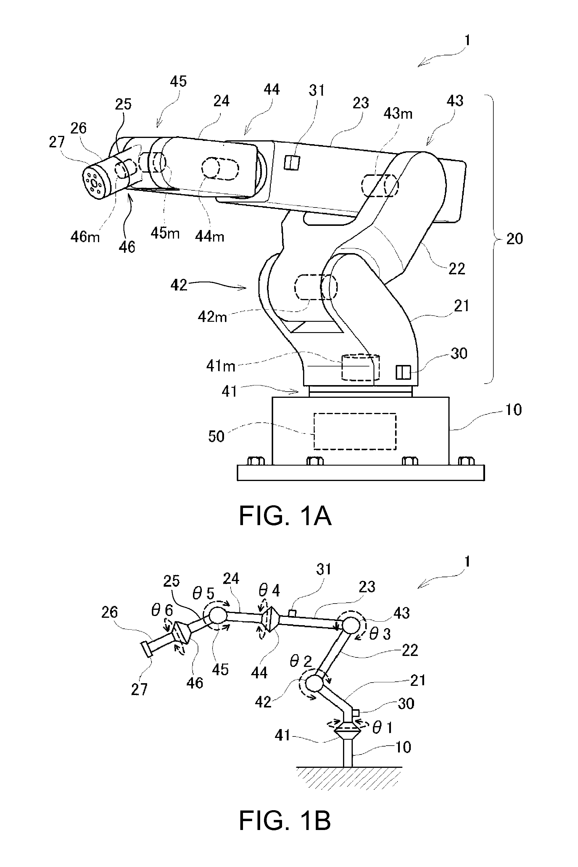
[0104]FIGS. 1A and 1B are explanatory diagrams showing the overall structure of a robot 1 according to a first embodiment. In FIG. 1A, a rough external shape of the robot 1 according to the first embodiment is shown.

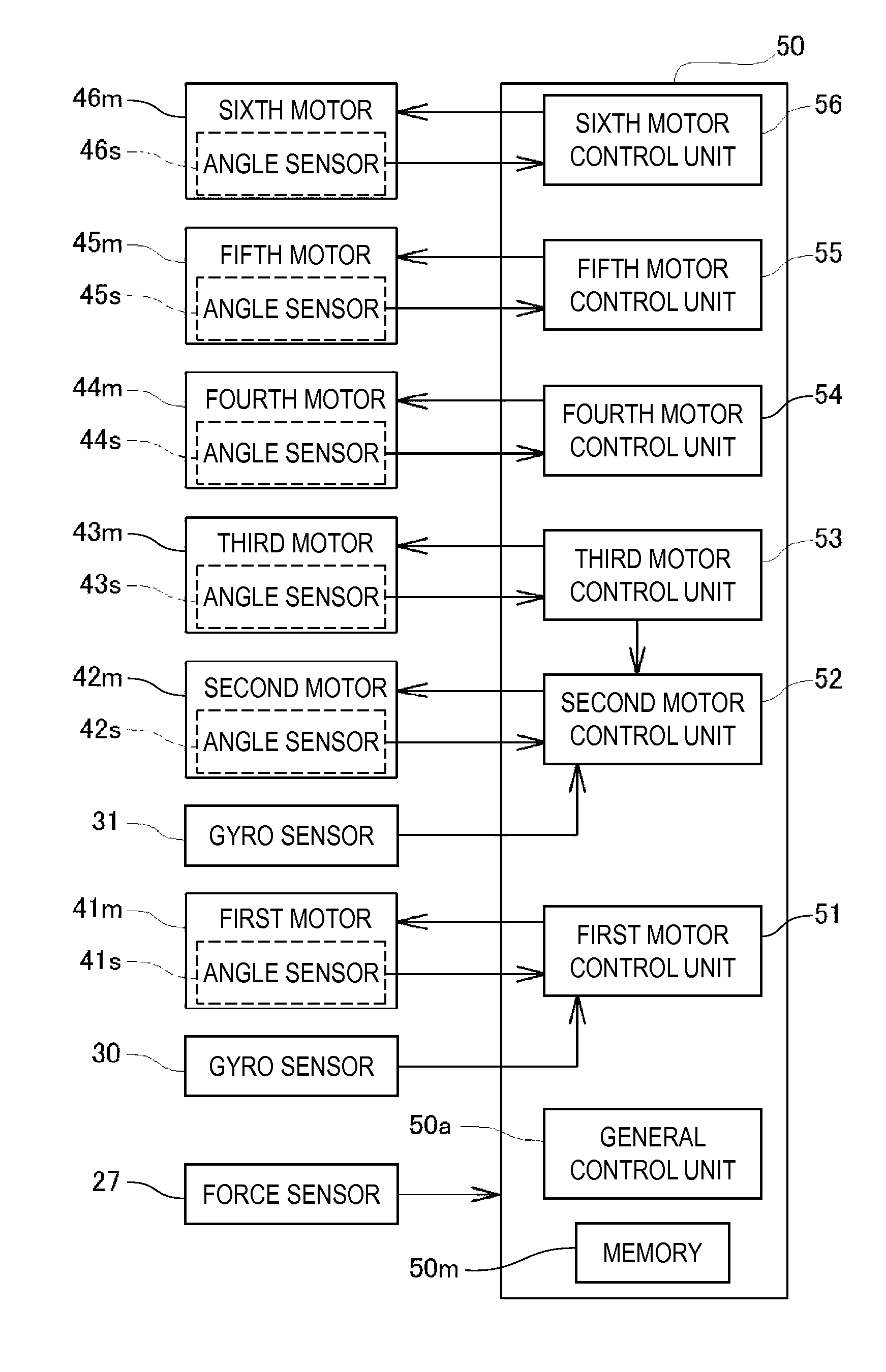
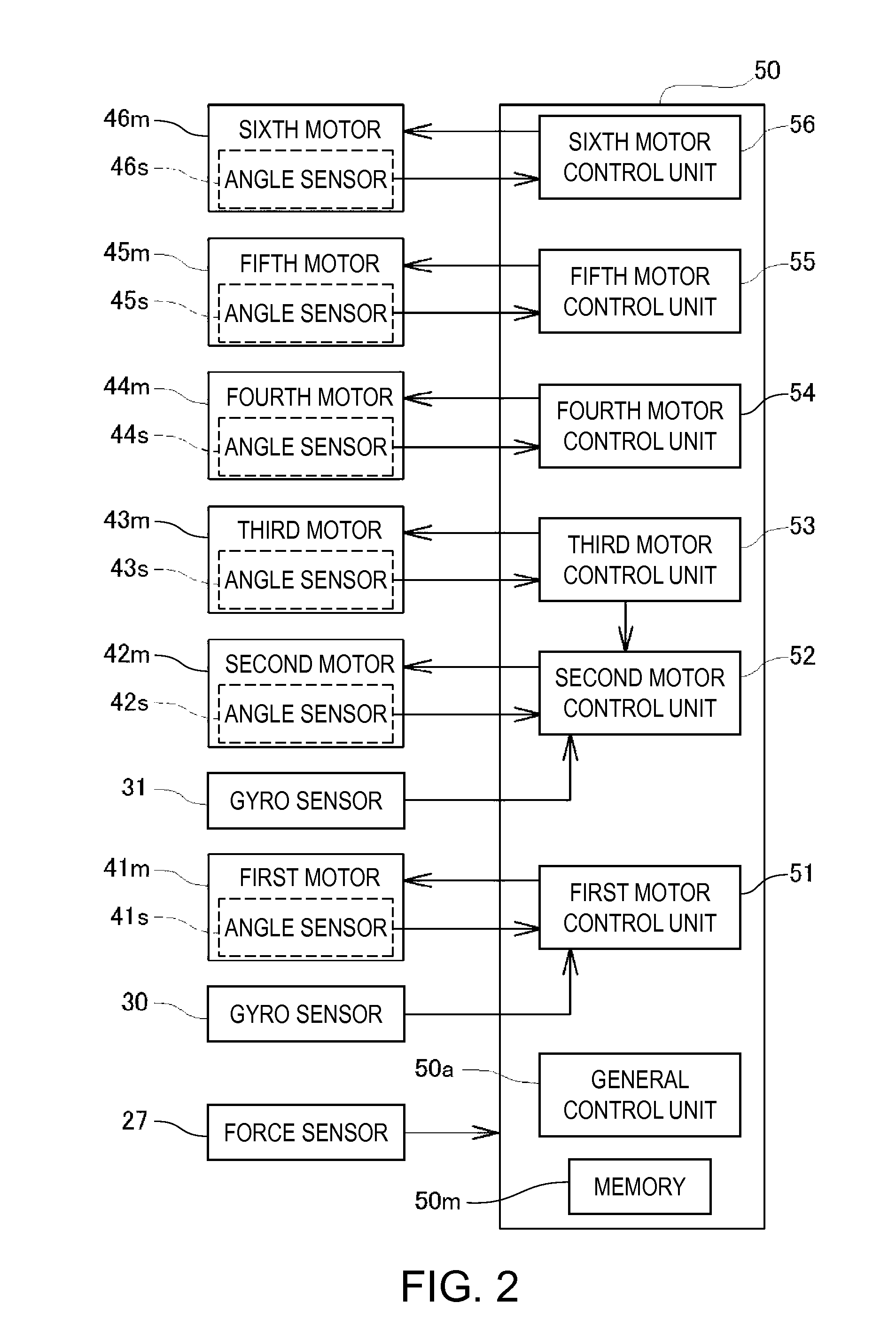
[0105]As shown in the figure, the robot 1 according to the first embodiment includes a base 10 set on the ground, a joint 41 functioning as a first joint, an arm 20 rotatably attached to the base 10 via the joint 41, and a control unit 50 mounted in the base 10 and configured to control the operation of the entire robot 1.

[0106]The arm 20 includes six arm members 21, 22, 23, 24, 25, and 26 and five joints 42, 43, 44, 45, and 46.

[0107]The arm member 21 functioning as a first arm member is rotatably attached to the base 10 by the joint 41 functioning as the first joint. The arm member 22 is bendably attached to the arm member 21 by the joint 42 functioning as a second joint. The arm member 23 is bendably attached to the arm member 22 by the joint 43.

[0108]Further, the arm ...

first modification

[0206]FIG. 13 is an explanatory diagram showing the configuration of a robot 2 according to a first modification. In the first embodiment, the gyro sensor 30 is mounted on the arm member 21 and the gyro sensor 31 is mounted on the arm member 23. However, a gyro sensor 32 may be mounted on the arm member 22 instead of the gyro sensor 31 mounted on the arm member 23.

[0207]In this case, control of the second motor 42m that drives the arm member 22 mounted with the gyro sensor 32 is the same as the control of the first motor 41m that drives the arm member 21 mounted with the gyro sensor 30. Therefore, control contents of the second motor control unit 52 in the robot 2 according to the first modification are the same as the control contents of the first motor control unit 51 explained with reference to FIG. 4.

[0208]Since the gyro sensor 31 is not mounted on the arm member 23 of the robot 2 according to the first modification, control of the third motor 43m that drives the arm member 23 i...

second modification

[0209]FIG. 14 is an explanatory diagram showing the configuration of a robot 3 according to a second modification. In the first embodiment and the first modification, the gyro sensor 30 of the arm member 21 and the gyro sensor 31 of the arm member 23 or the gyro sensor 32 of the arm member 22 are mounted. However, in addition to the gyro sensor 30 of the arm member 21 and the gyro sensor 31 of the arm member 23, the gyro sensor 32 may be mounted on the arm member 22.

[0210]In this case, control of the second motor 42m that drives the arm member 22 mounted with the gyro sensor 32 and control of the third motor 43m that drives the arm member 23 mounted with the gyro sensor 31 are the same as control of the first motor 41m that drives the arm member 21 mounted with the gyro sensor 30. Therefore, control contents of the second motor control unit 52 and control contents of the third motor control unit 53 in the robot 3 according to the second modification only have to be the same as the c...


PUM


Abstract

A robot includes a plurality of joints including a first joint and a second joint that rotates in a direction different from a rotation direction of the first joint, a plurality of arm members including a first arm member provided to be rotatable with respect to a base via the first joint, and a first angular velocity sensor provided in the first arm member or the first joint. A first inertial sensor is provided in the first arm member (or a portion that rotates together with the first arm member in the first joint). The plurality of joints are controlled on the basis of an output of the first inertial sensor.

Description

BACKGROUND[0001]1. Technical Field[0002]The present invention relates to a robot.[0003]2. Related Art[0004]There is known a robot including an arm in which a plurality of arm members are connected by joints. It is possible to cause the robot to perform various kinds of work by attaching a robot hand and the like to the distal end of the arm. However, when the robot hand or the like is moved to a target position and stopped in order to perform work, the work cannot be started because the distal end of the arm oscillates for a while.[0005]Therefore, there has been proposed a technique for mounting an inertial sensor on the distal end side of an arm and suppressing oscillation of the arm by controlling movements of joints of the arm to reduce an output of the inertial sensor (JP-A-2005-242794 (Patent Literature 1)).[0006]However, among robots including a large number of joints, there is a robot that moves a certain joint to thereby change the directions of rotation axes of the joints a...

Claims


Application Information

Patent Timeline
IPC IPC(8): B25J9/16
CPCB25J9/1651Y10S901/28Y10S901/09G05B2219/37134G05B2219/39195B25J13/088B25J9/1641
Inventor GOMI, AKIHIROMOTOYOSHI, MASAKITOSHIMITSU, SHUNSUKENIU, AKIOASADA, ATSUSHI
Owner SEIKO EPSON CORP
Why Eureka
Try Eureka