V/f control method for suppressing current oscillation of induction motor

Active Publication Date: 2016-08-04
EATON INTELLIGENT POWER LIMITED
View PDF2 Cites 2 Cited by
  • Summary
  • Abstract
  • Description
  • Claims
  • Application Information

AI Technical Summary

Benefits of technology

The technical effect of this patent is to provide a better method for controlling the voltage and frequency of an induction motor to prevent it from shaking and improving its stability. This is achieved by introducing two coefficients that can vary independently from each other, which allows for flexible selection of different values to achieve the best results.

Problems solved by technology

If the magnetic flux is very small, the iron core of the motor cannot be fully utilized and therefore cannot output a high torque.
However, if the magnetic flux is very large, the iron core of the motor will be saturated, which leads to an excessive exciting current and even a failure of the motor.
However, when a frequency converter controls the motor, the oscillation of the output current may occur for the following reasons.
The harmonic current will cause torque ripples.
Since a dead time which can affect the fundamental voltage is set in the converter to prevent the bridge arms of the inverter from shoot-through, the low-order harmonic component is enlarged, which leads to is a distortion of the current, especially when the motor is in a no-load condition.
In the existing technology for suppressing the oscillation by fine tuning of the frequency output, since both of the reactive current isde and the active current isqe are multiplied by the same coefficient, only the gain coefficient and the cut-off frequency of the filter are adjustable, and thereby the effect of the control method for suppressing the oscillation is limited.

Method used


Image

  • V/f control method for suppressing current oscillation of induction motor
  • V/f control method for suppressing current oscillation of induction motor
  • V/f control method for suppressing current oscillation of induction motor

Examples


Embodiment Construction

[0051]In order to make the objects, the technical solutions and the advantages of the present invention more clear, the present invention will be explained in detail in conjunction with the following specific embodiments. It should be understood that the specific embodiments described here are only used to explain the present invention but not used to limit the present invention.

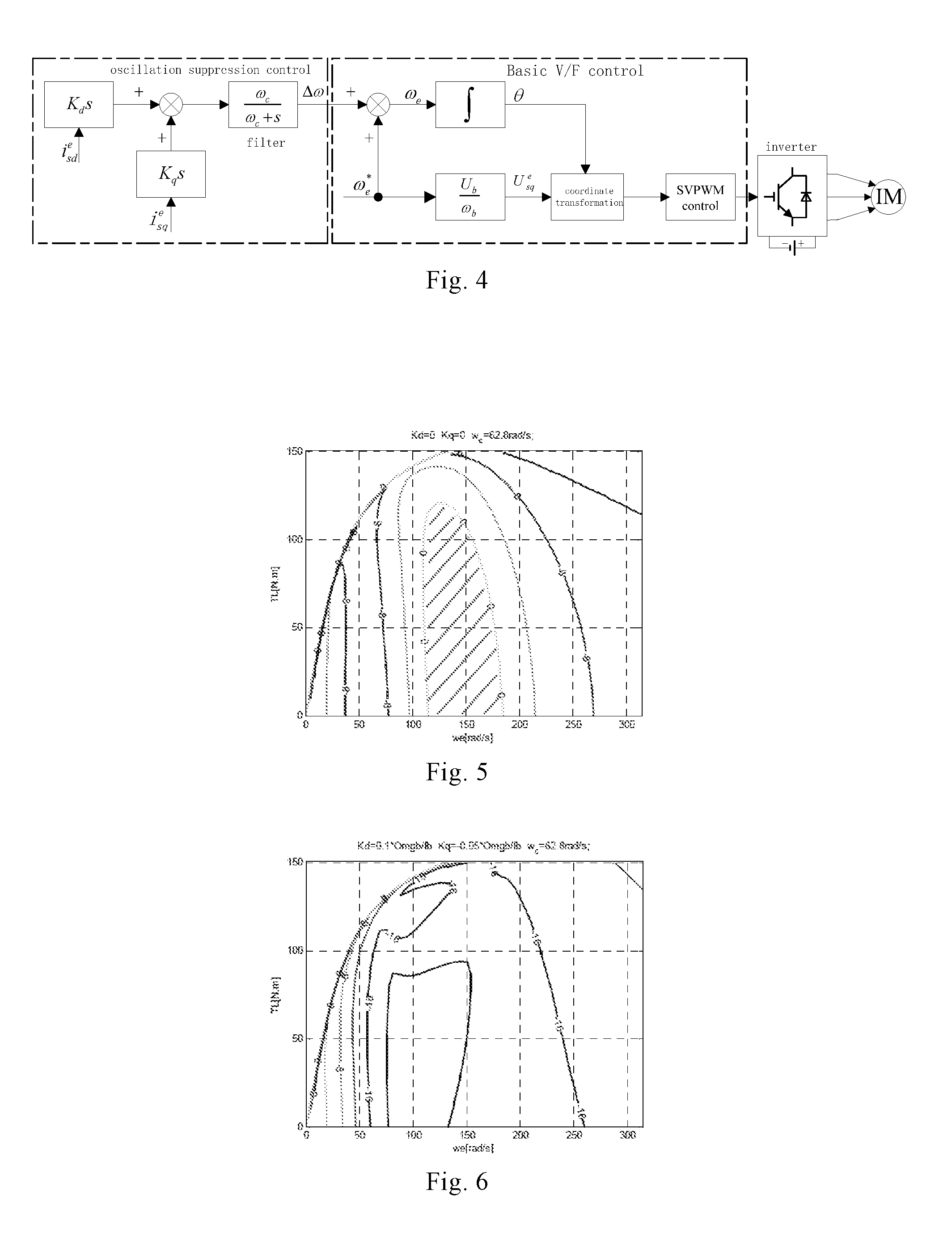
[0052]The present embodiment provides a V / F control method for an induction motor, a block diagram of which is shown in FIG. 4. The method comprises the steps of:

[0053]1) extracting a reactive current isde and an active current isqe, and performing a differential calculation on them respectively to obtain a differential Δisde of the reactive current and a differential Δisqe of the active current;

[0054]2) multiplying the differential Δisde of the reactive current and the differential Δisqe of the active current by coefficients Kd and Kq, respectively, wherein Kd and Kq can vary independently from each other;

[...


PUM


Abstract

The present invention provides a V / F control method for an induction motor comprising: extracting a reactive current and an active current and performing a differential calculation on them respectively to obtain a differential of the reactive current and a differential of the active current; multiplying the differential of the reactive current and the differential of the active current by a first coefficient and a second coefficient respectively; obtaining the sum of the result of multiplying the differential of the reactive current by the first coefficient and the result of multiplying the differential of the active current by the second coefficient; applying low-pass filtering on the sum to obtain a compensation; and superposing the compensation onto an original given angular frequency to perform V / F control.

Description

FIELD OF THE INVENTION[0001]The present invention relates to a control method for an induction motor and, more particularly, to a V / F control method for an induction motor.BACKGROUND OF THE INVENTION[0002]Induction motor, also known as asynchronous motor, is an AC motor which drives a rotor to rotate with an electromagnetic torque produced by an interaction between a rotating magnetic field formed by a stator winding and a magnetic field of induced currents in a rotor winding. FIG. 1 shows an equivalent circuit of an induction motor.[0003]Generally, the value of the air-gap flux is kept unchanged during the adjustment of the speed of the induction motor. If the magnetic flux is very small, the iron core of the motor cannot be fully utilized and therefore cannot output a high torque. However, if the magnetic flux is very large, the iron core of the motor will be saturated, which leads to an excessive exciting current and even a failure of the motor. For this reason, frequency convers...

Claims


Application Information

Patent Timeline
IPC IPC(8): H02P27/04H02P21/05
CPCH02P21/05H02P27/047H02P23/04
Inventor LEE, KEVINLI, DAWEIYU, ANBO
Owner EATON INTELLIGENT POWER LIMITED
Why Eureka
Try Eureka