Sun gear drive arrangement

Active Publication Date: 2018-02-01
ROLLS ROYCE PLC
View PDF0 Cites 2 Cited by
  • Summary
  • Abstract
  • Description
  • Claims
  • Application Information

AI Technical Summary

Benefits of technology

[0010]Providing flexible drive shaft in such away allows the various misalignments between

Problems solved by technology

However, the introduction of the reduction gearing in large gas turbine engines leads to parasitic loads which result from an accumulation build tolerances and thermo-mechanical movement in service.
The parasitic loads can result in significant

Method used


Image

  • Sun gear drive arrangement
  • Sun gear drive arrangement
  • Sun gear drive arrangement

Examples


Embodiment Construction

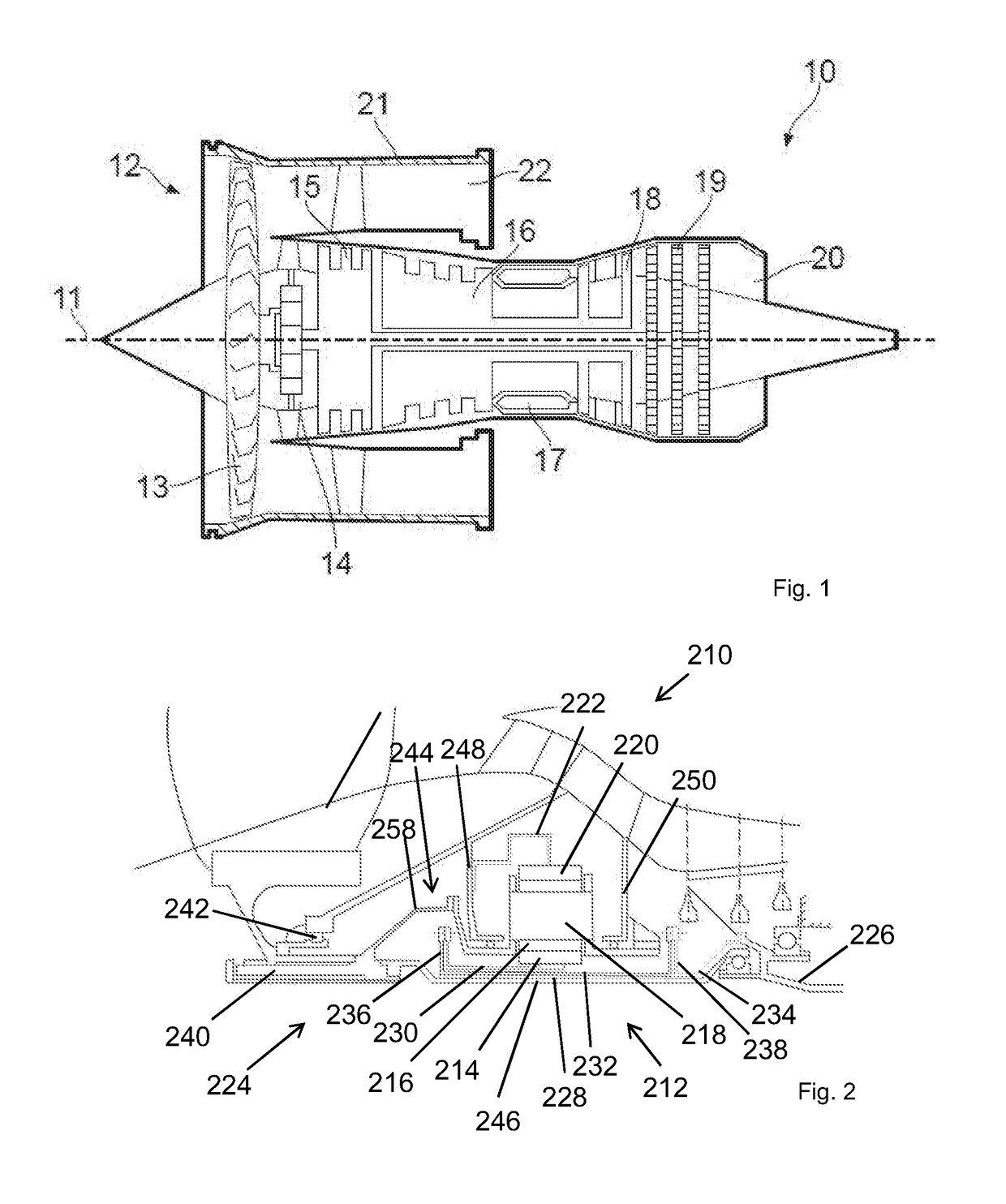
[0030]FIG. 1 shows a geared gas turbine engine 10 having a principal axis of rotation 11 and, in axial flow series, a fan 12, a gear train 14, a low pressure compressor 15, a high pressure compressor 16, a combustor 17, a high pressure turbine 18 and a low pressure turbine 19. Interconnecting shafts drivable connect the low pressure compressor and low pressure turbine, and the high pressure compressor and high pressure turbine.

[0031]The low 15 and high 16 pressure compressors progressively compress air from an inlet downstream of a fan 12 to an outlet in flow proximity to the combustor 17. Compressed air flows from the high pressure compressor 18 into the combustor 17 where fuel is added and the mixture burnt. The combusted gas expands through and drives the high 18 and low 19 pressure turbines in flow series before being exhausted from the core nozzle 20.

[0032]The fan 12 is located at the front of the engine to provide air for the inlet of the compressors and the main propulsive fl...


PUM


Abstract

Disclosed is a gas turbine engine comprising: a low pressure spool having a low pressure compressor and a low pressure turbine connected by a low pressure shaft; a reduction gear train having a sun gear, a carrier having a plurality of planet gears attached thereto, and a ring gear, wherein the sun gear is driveably connected to the low pressure shaft, and either of carrier and ring gear provides an output drive connected to a propulsive fan; wherein the connection between the low pressure shaft and the sun gear includes a flexible drive shaft having serially connected concentrically nested first and second input shafts between the low pressure shaft and sun gear.

Description

TECHNICAL FIELD OF INVENTION[0001]This invention relates to an input drive shaft for a geared turbo fan power gearbox.BACKGROUND OF INVENTION[0002]Current trends in gas turbine engines are moving towards so-called geared turbofan engines in which the fan is driven through a reduction gear train. The gear train allows the low pressure spool to be driven at higher rotational speeds which provides for a more efficient lighter engine core, whilst reducing the speed of the fan allows it to be a larger diameter thereby providing a higher bypass ratio. The reduction gear trains may be epicyclically configured where the fan is driven via the carrier of a planetary configuration, or a star configuration where the planet gears are fixed and the fan shaft is driven by the ring or star gear. The gear train may be a compound configuration as known in the art.[0003]However, the introduction of the reduction gearing in large gas turbine engines leads to parasitic loads which result from an accumul...

Claims


Application Information

Patent Timeline
IPC IPC(8): F02C7/36F16H57/00F16D3/76F16H1/28F02K3/06F16C1/02
CPCF02C7/36F02K3/06F16C1/02F05D2260/40311F16H1/28F16H57/0025F16D3/76F05D2240/40F05D2240/61F05D2240/62
Inventor THORNTON, STEWART T.SWIFT, ANDREW
Owner ROLLS ROYCE PLC
Why Eureka
Try Eureka