Wavelength division multiplexing optical communication system

Inactive Publication Date: 2006-08-08
FUJITSU LTD
View PDF9 Cites 15 Cited by
  • Summary
  • Abstract
  • Description
  • Claims
  • Application Information

AI Technical Summary

Benefits of technology

[0014]In such a WDM optical communication system, since the demultiplexing process or the multiplexing process, which is performed in accordance with a plurality of wavelength regions into which the signal wavelength band of the WDM signal light is divided, is performed in a state where the bandwidth for each optical signal is set to the integral multiple of the wavelength width unit and also approximately coincides with the wavelength arrangement spacing corresponding to each bit rate, it is possible to demultiplex or multiples the optical signals in a state where a required bandwidth corresponding to each bit rate is ensured. As a result, it becomes possible to realize a WDM optical communication that accommodates optical signals of a plurality of bit rates at different wavelength arrangement spacing efficiently.

Problems solved by technology

That is, if the flatness is insufficient, then a part of signal light component is cut off, thus producing waveform distortion.
In trying to demultiplex optical signals at 50 GHz spacing using only an optical filter using an AWG, a film filter or the like, it is difficult to ensure flatness in a filter band.
However, since a required bandwidth for optical signals with each wavelength exists according to the transmission speed, there is a limit when trying to narrow the wavelength spacing.
Therefore, if the wavelength spacing of each optical signal is made too narrow, such bandwidth cannot be ensured, resulting in a problem in that the transmission cannot be performed.
For example, if it is attempted to transmit an optical signal with a transmission speed of 40 Gb / s at 50 GHz spacing, crosstalk with neighboring wavelengths is predicted, so the optical transmission at such wavelength spacing is considered to be difficult.
In order to use the conventional WDM optical communication system in the state where optical signals of various bit rates are intermixed, since it is necessary to select the wavelength spacing from the beginning (designing stage) so as to be adapted to an optical signal of a maximum bit rate supported by the system, there is a problem in that accommodation efficiency of optical signals of lower bit rates becomes poor.
Therefore, there is another problem in that it is difficult to respond to higher bit rates flexibly,

Method used


Image

  • Wavelength division multiplexing optical communication system
  • Wavelength division multiplexing optical communication system
  • Wavelength division multiplexing optical communication system

Examples


Embodiment Construction

[0034]Firstly, a basic constitution of the present invention will be described using drawings.

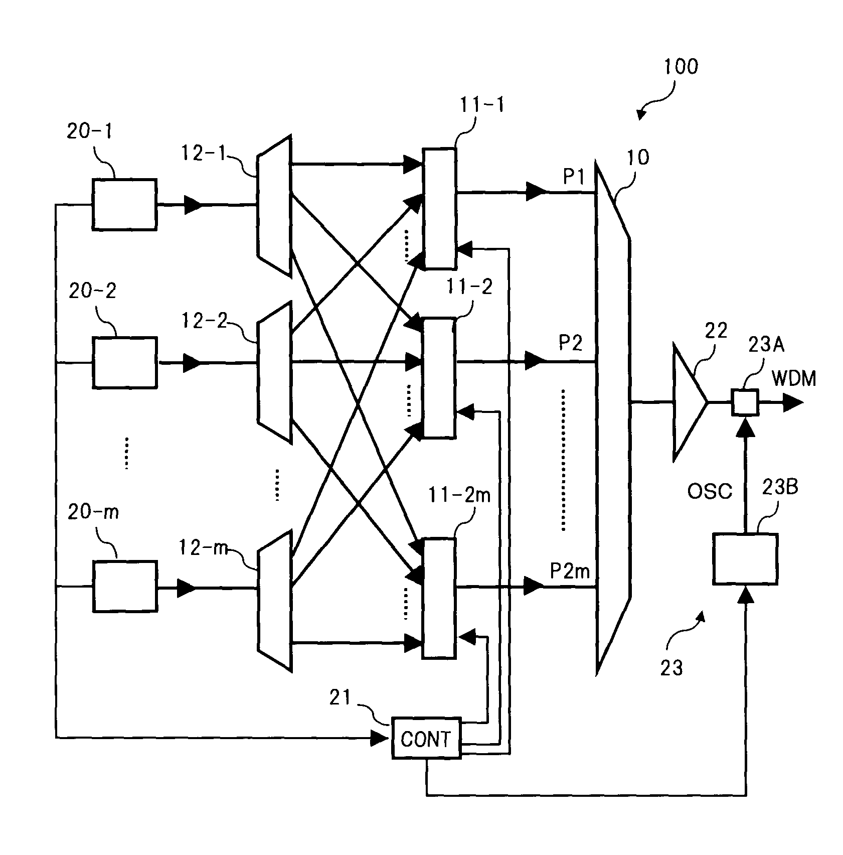
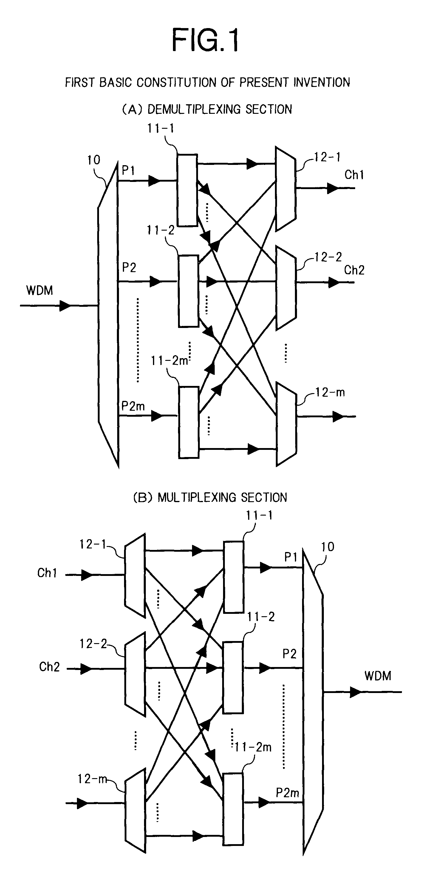
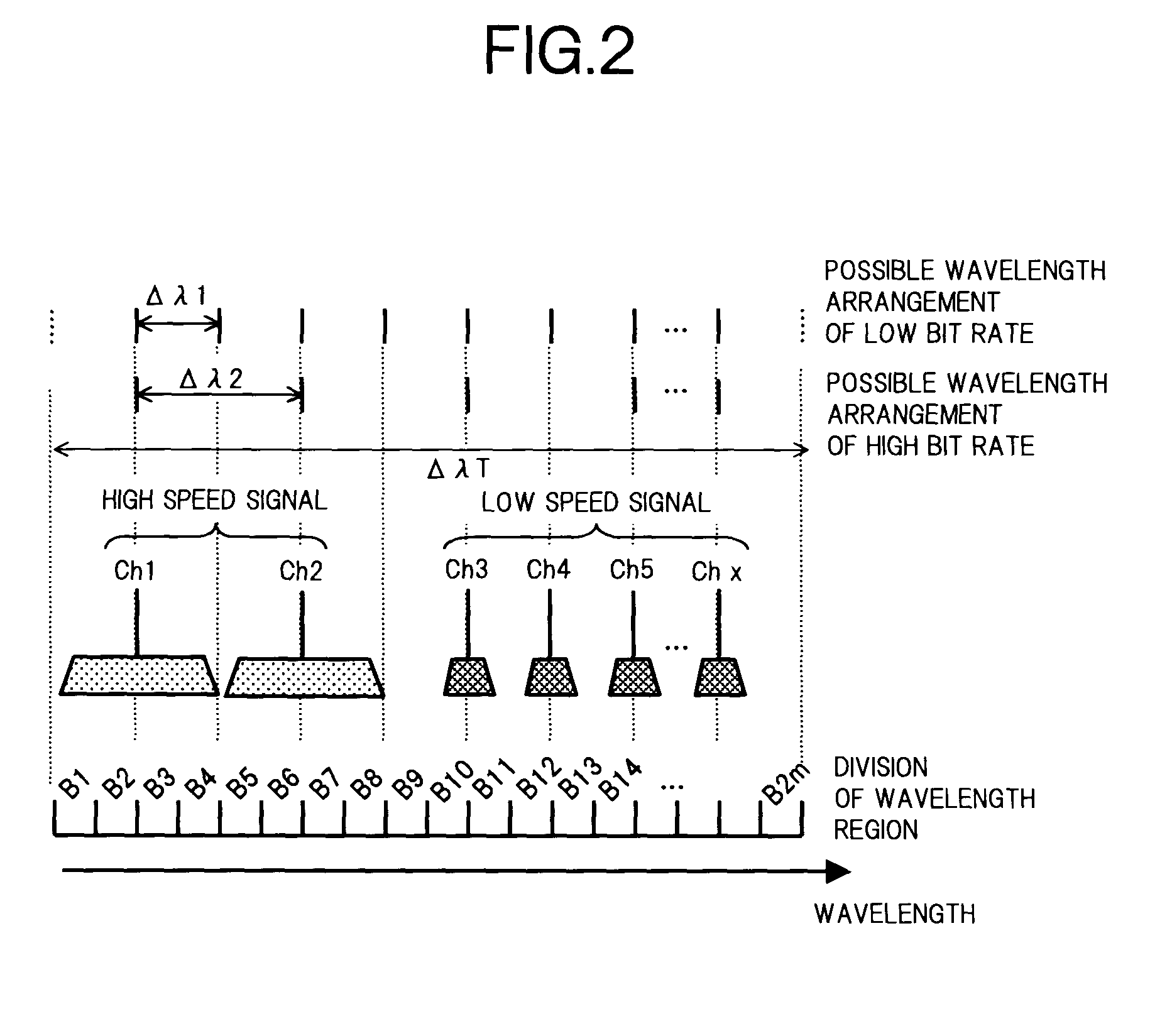
[0035]FIG. 1 is a block diagram showing a first basic constitution of the present invention, to be applied to a WDM optical communication system, in which (A) is a constitution of a demultiplexing section that demultiplexes WDM signal light into respective wavelengths, and (B) is a constitution of a multiplexing section that multiplexes optical signals with respective wavelengths. Furthermore, FIG. 2 shows an example of an assignment of wavelength regions corresponding to the basic constitution of FIG. 1. Note, in the following description, the constitution of the demultiplexing section will be described. Since the constitution of the multiplexing section can be considered similarly by reversing an input and output relationship in the demultiplexing section, corresponding parts are denoted by the same symbols and the description thereof is omitted.

[0036]In (A) of FIG. 1, the demultiplexing ...


PUM


Abstract

The present invention aims to provide a WDM optical communication system that can arrange efficiently optical signals of a plurality of bit rates at different wavelength spacing. To this end, for example, a basic constitution of a demultiplexing section to be applied to the WDM optical communication system of the present invention is provided with a demultiplexer that demultiplexes WDM signal light into 2m components in accordance with a plurality of wavelength regions set according to minimum wavelength spacing, 2m optical switches, each of which has one input port to which light from the demultiplexer is input, and a plurality of output ports, that selects one of the plurality of output ports to connect it to the input port, and m multiplexers that each multiplexes each output light of the 2m optical switches, wherein switching operations of the optical switches is set such that the bandwidth of each optical signal is approximately the same as the wavelength arrangement spacing corresponding to each bit rate.

Description

[0001]This application is a continuing application, filed under 35 U.S.C. § 111(a), of International Application PCT / JP01 / 08263, filed Sep. 21, 2001, it being further noted that foreign priority benefit is based upon Japanese Patent Application 2000-304315, filed Oct. 4, 2000.TECHNICAL FIELD[0002]The present invention relates to a wavelength-division multiplexing (WDM) optical communication system for transmitting a plurality of optical signals with different wavelengths collectively. In particular, the invention relates to an optical transmission terminal apparatus, an optical reception terminal apparatus and an optical add drop apparatus, that accommodate optical signals of a plurality of bit rates arranged at different wavelength spacing, and a WDM optical communication system constituted using these apparatuses.BACKGROUND ART[0003]In recent years, optical communication systems of further longer distance and further larger capacity have been required for multimedia networks, alon...

Claims


Application Information

Patent Timeline
IPC IPC(8): H04J14/02H04B10/04H04B10/077G02F1/31H04B10/2507H04B10/27H04B10/29H04B10/296H04J14/00H04J14/08H04Q3/52H04Q11/00
CPCH04J14/0209H04J14/0212H04J14/0213H04J14/0224H04J14/026H04Q11/0062H04Q11/0005H04Q2011/0016H04Q2011/0075
Inventor TOMOFUJI, HIROAKIONAKA, HIROSHICHIKAMA, TERUMI
Owner FUJITSU LTD
Why Eureka
Try Eureka