Fluid Turbine with Control System

a control system and turbine technology, applied in the direction of renewable energy generation, greenhouse gas reduction, sustainable manufacturing/processing, etc., can solve the problems of reducing the efficiency of the generator, and ineffective drag differential, so as to achieve effective torque

Inactive Publication Date: 2018-02-01
RAO VIJAY
View PDF44 Cites 7 Cited by
  • Summary
  • Abstract
  • Description
  • Claims
  • Application Information

AI Technical Summary

Benefits of technology

[0013]The symmetry of each airfoil allows it to generate lift on either face, depending on its angle of attack to the wind direction. An angle of attack parallel to the wind direction will generate no lift in either direction.
[0014]Airfoils rotate about their respective airfoil axes as the armatures rotate about the main axle. The rotation of the armatures about the main axle is called an orbit. As the armatures orbit the main axle, each airfoil rotates about its respective airfoil axle to produce a desired angle of attack. The airfoils are not mechanically bound to each other, enabling them to have differing angles of attack. Motors adjust the angles of attack for each airfoil, facilitating the ability of each airfoil to continually generate lift at different positions in the orbit.
[0015]As airfoils orbit the main axle, the angle of attack reverses from the most windward position of the orbit to the most leeward position. The symmetry of each airfoil affords the ability to generate effective torque at both the windward and leeward arcs of the orbit.

Problems solved by technology

The drag differential is inefficient, but effective at rotating the turbine.
This inherently creates drag, detracting from the efficiency of the generator, but also creating an uneven dynamic stress on the turbine in the wind's direction.
This might have some effect on the degree of drag when the blades’ angles of attack are leeward, but the trailing edge of each blade is still forced into the wind, creating inordinate drag on the turbine.
This configuration is flawed in that it emphasizes the use of drag for generating power, whereas other aerodynamic forces are more efficient and less strenuous on the turbine.

Method used


Image

  • Fluid Turbine with Control System
  • Fluid Turbine with Control System
  • Fluid Turbine with Control System

Examples


Embodiment Construction

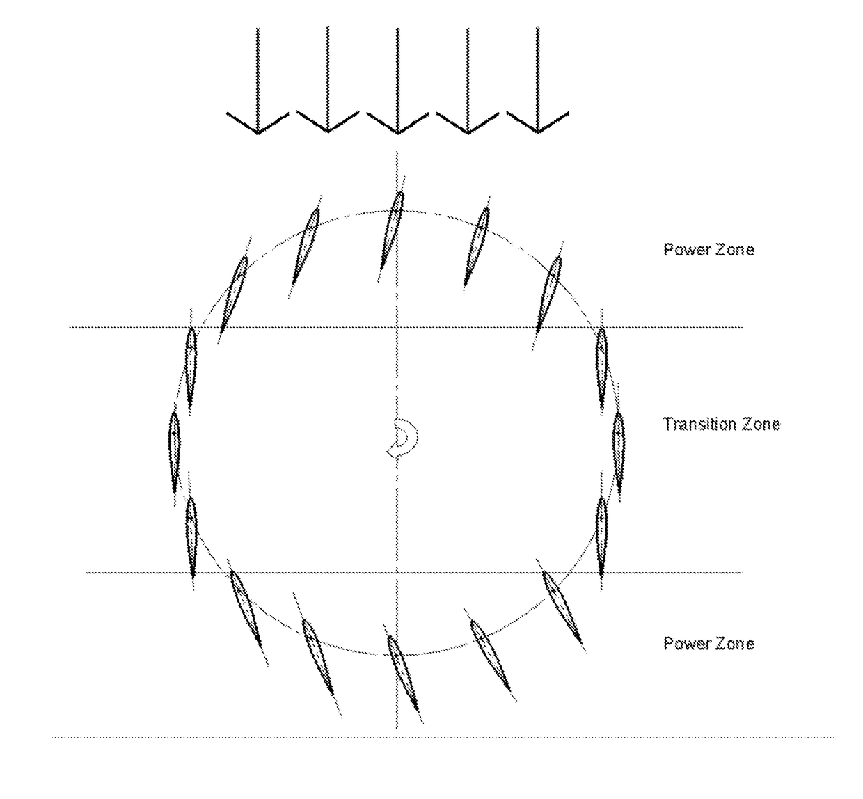
[0025]The invention is a vertical axis power generator and its control system. This application will primarily discuss one embodiment of the invention, which converts wind energy into electric power, but other embodiments harnessing the power of other moving fluids are envisioned, specifically water.

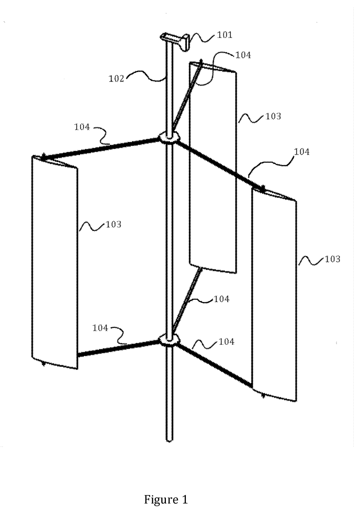
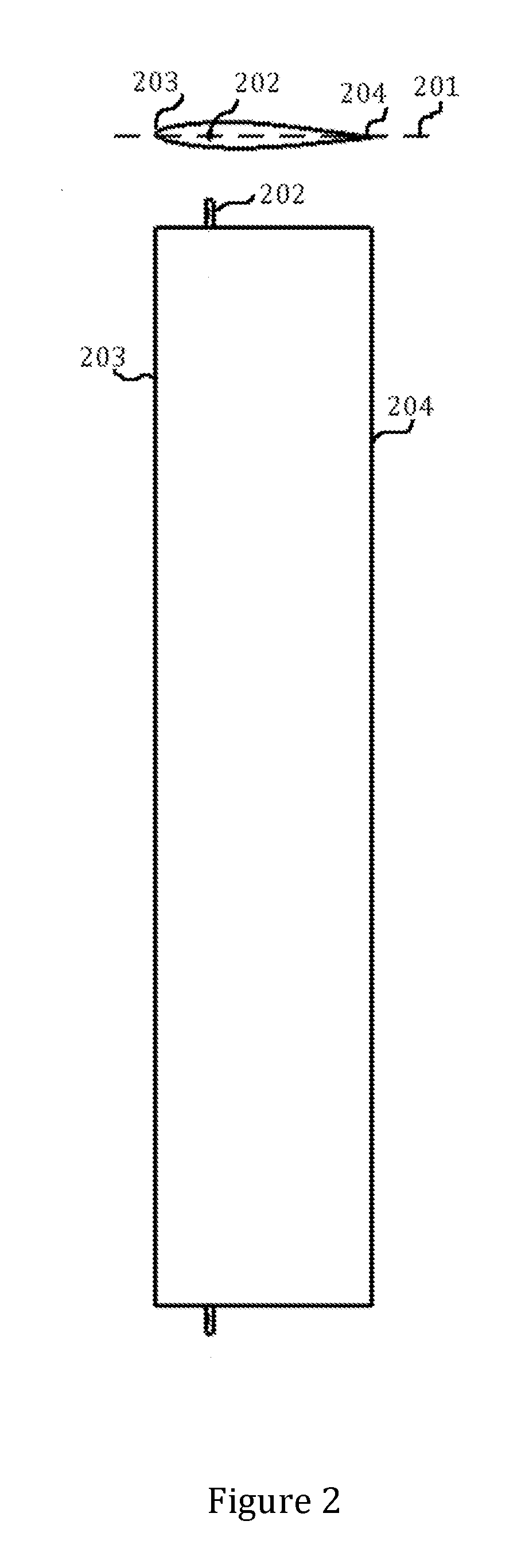
[0026]One embodiment of the invention is a vertical axis wind turbine with three foils. See FIG. 1. Other embodiments of the invention may contain more than three airfoils. The invention includes a means for constantly measuring wind direction. In this embodiment, a wind vane 101 is attached to the top of a central shaft 102. A rotary encoder measures the rotational position of the wind vane. For power generation based on wind, the foils are airfoils. Alternative embodiments which use water as the moving fluid have hydrofoils.

[0027]The three airfoils 103 are attached to the central shaft by three sets of armatures 104. The armatures rotate in a clockwise or counterclockwise direction abo...


PUM


Abstract

A vertical axis fluid turbine for mechanical and electrical power generation is disclosed. The turbine is comprised of at least three camber-less symmetrical foils rotating about a main axis. Each foil is capable of independent rotation about its own respective axis. A closed loop feedback control system orients the foils to consistently maintain a forward edge into the flow of the fluid. Each foil generates lift in the forward and rearward arcs of rotation, while minimizing drag.

Description

CROSS-REFERENCE TO RELATED APPLICATIONS[0001]This application is a continuation-in-part of U.S. application Ser. No. 14 / 614,663, filed on Feb. 5, 2015.BACKGROUNDTechnical Field[0002]The present invention is directed to alternative energy power generation and control systems, converting fluid energy into mechanical and electrical power.Background Art[0003]Wind turbines have aided humans with power generation for thousands of years. There are two basic categories, horizontal axis and vertical axis. Horizontal axis wind turbines, currently use blades oriented around a hub, similar to airplane propellers, and turn a horizontal axis,[0004]Vertical axis wind turbines utilize vertically oriented blades, which rotate around a vertical axis. They are beneficial over horizontal axis wind turbines in that they do not need repositioning with changing wind direction.[0005]There are multiple types of vertical axis wind turbines. One popular model is the Savonius type (U.S. Pat. No. 1,766,765), wh...

Claims


Application Information

Patent Timeline
Patent Type & Authority Applications(United States)
IPC IPC(8): F03D7/06F03D9/25F03D17/00F03D3/00
CPCF03D3/068F03D7/06F05B2270/602Y02E10/74Y02P80/10F03D3/005F03D9/25F03D17/00
Inventor RAO, VIJAY
Owner RAO VIJAY
Why Eureka
Try Eureka