
Sliding bearing

a technology of sliding bearings and rollers, which is applied in the direction of sliding contact bearings, crankshaft bearings, mechanical equipment, etc., can solve the problems of large friction, and achieve the effects of reducing friction, reducing the amount of total outflow oil, and reducing the generation of oil film pressur

Inactive Publication Date: 2018-02-01
TAIHO INDUSTRIES CO LTD
View PDF1 Cites 0 Cited by
  • Summary
  • Abstract
  • Description
  • Claims
  • Application Information

AI Technical Summary

Benefits of technology

The patent text describes a design feature for a bearing that reduces friction and limits the amount of oil that leaks out. This is achieved by using a narrow groove that doesn't hindle the formation of an oil film pressure, which increases the amount of lubricant oil that can be used and reduces the amount of oil that leaks out. Additionally, a chamfered section in the peripheral section of the bearing helps to smoothly draw in the lubricant oil, further increasing the amount of oil used and reducing friction.

Problems solved by technology

Conventionally known sliding bearings, for supporting a crankshaft of an engine, having a halved structure in which two members obtained by halving a cylindrical member are combined are plagued by a large friction due to high viscosity of oil during a cold engine operation.

Method used


Image

  • Sliding bearing
  • Sliding bearing
  • Sliding bearing

Examples


Embodiment Construction

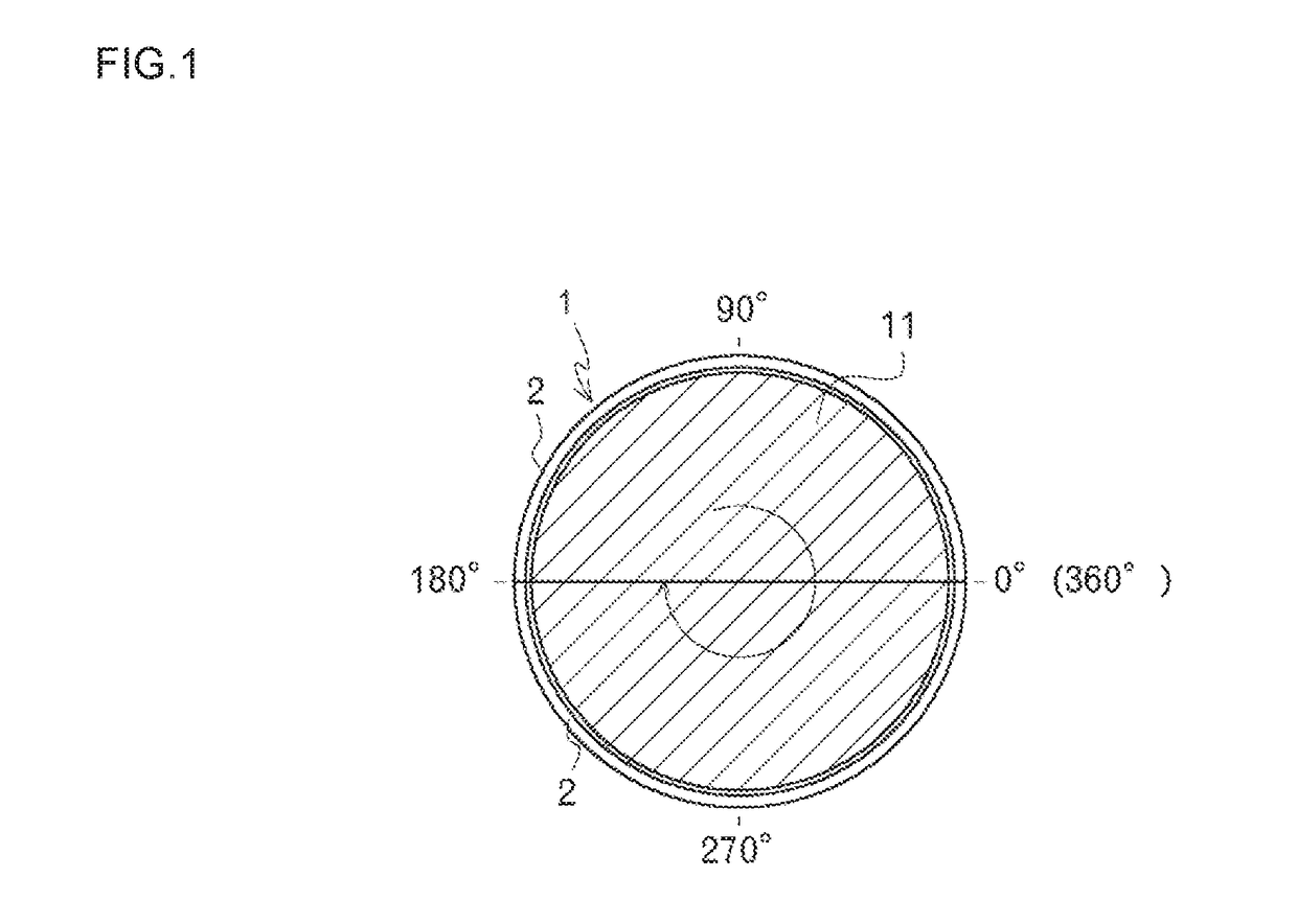
[0017]An embodiment of the invention is described below. FIG. 1 is a front view of a sliding bearing 1, with a vertical direction of the sheet defined as an upper and lower direction, and a direction between a closer side and a farther side of the sheet defined as an axial direction (front and rear direction).

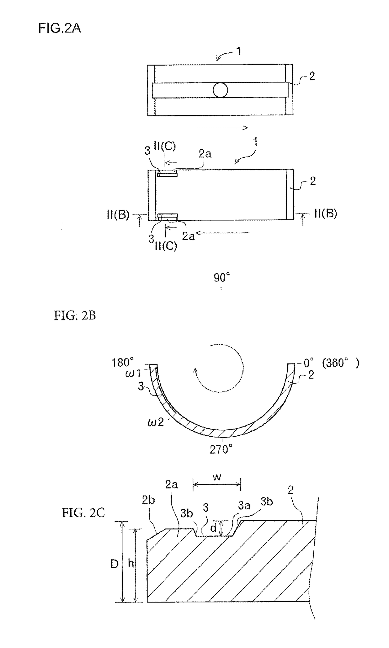
[0018]First of all, halved members 2 as parts of the sliding bearing 1 according to an embodiment of the present invention are described with reference to FIG. 1 and FIGS. 2A-2C.

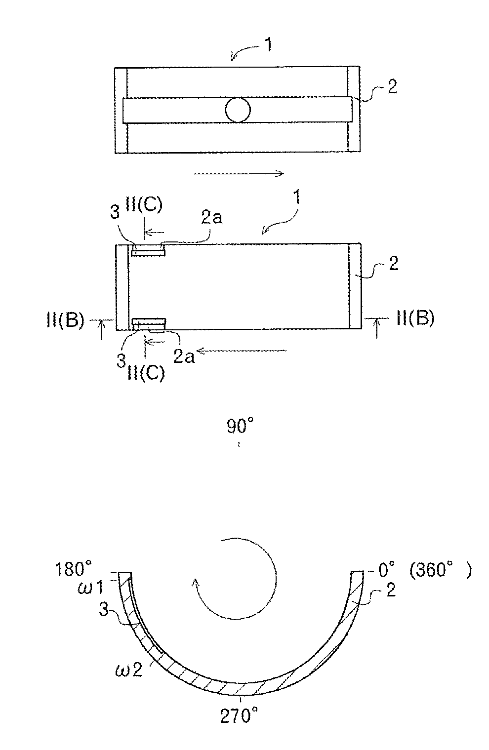
[0019]The sliding bearing 1 is a cylindrical member, and is applied to a sliding bearing structure of a crankshaft 11 of an engine as illustrated in FIG. 1. The sliding bearing 1 includes two halved members 2 and 2. The two halved members 2 and 2 have shapes formed by halving a cylinder in a direction parallel to the axial direction of the cylinder, and each have a semicircular cross-sectional shape. In the present embodiment, the halved members 2 and 2 are arranged in the upper and lower direction with...


PUM


Abstract

Provided is a sliding bearing capable of achieving a friction reduction effort and limiting A total outflow oil amount. This sliding bearing has vertically disposed members which are formed by halving a cylinder in the direction parallel to the axial direction of the cylinder wherein narrow grooves are provided on an axial end of the lower halved member in a circumferential direction on the downstream side in the rotation direction; peripheral sections are formed outward from the narrow grooves in the axial direction so as to be lower than a contact surface between the sliding bearing and a crankshaft, and when viewed in a cross-section perpendicular to the longitudinal direction of the peripheral section, a chamfered section is formed at an outer edge section in the axial direction of the peripheral section.

Description

CROSS REFERENCE TO RELATED APPLICATIONS[0001]This is the U.S. national stage of application No. PCT / JP2016 / 055948, filed on Feb. 26, 2016. Priority under 35 U.S.C. § 119(a) and 35 U.S.C. § 365(b) is claimed from Japanese Application No. 2015-039113, filed on Feb. 27, 2015, the disclosures of which are also incorporated herein by reference.TECHNICAL FIELD[0002]The present invention relates to a technique of a sliding bearing, and to a technique of a sliding bearing including vertically disposed halved members which are formed by halving a cylinder in a direction parallel to an axial direction of the cylinder.BACKGROUND ART[0003]Conventionally known sliding bearings, for supporting a crankshaft of an engine, having a halved structure in which two members obtained by halving a cylindrical member are combined are plagued by a large friction due to high viscosity of oil during a cold engine operation. Thus, one known bearing has relief portions (narrow grooves) formed in both ends of the...

Claims


Application Information

Patent Timeline
Patent Type & Authority Applications(United States)
IPC IPC(8): F16C17/02F16C33/10F16C9/02F16C33/08
CPCF16C17/022F16C33/08F16C33/1025F16C9/02F16C2360/22F16C33/046F16C33/1065F16C17/02F16C33/10
Inventor SEKI, DAISUKETAKAGI, YUJI
Owner TAIHO INDUSTRIES CO LTD
Features
  • Generate Ideas
  • Intellectual Property
  • Life Sciences
  • Materials
  • Tech Scout
  • Unparalleled Data Quality
  • Higher Quality Content
  • 60% Fewer Hallucinations
Learn More