Ball type self-induction self-rotation fire extinguishing device

A fire extinguishing device and self-sensing technology, applied in the field of ball-type self-induction and self-rotating fire extinguishing devices, can solve the problems of high storage requirements, poor fire extinguishing effect, suffocation of personnel, etc., and achieve the goal of increasing safety, reducing safety, and preventing re-ignition Effect

Active Publication Date: 2020-05-29
朱香芽
View PDF7 Cites 6 Cited by
  • Summary
  • Abstract
  • Description
  • Claims
  • Application Information

AI Technical Summary

Problems solved by technology

[0004] The purpose of the present invention is to solve the disadvantages in the prior art that the storage requirements of carbon dioxide fire extinguishers are high, the fire extinguishing effect is poor in areas with good air circulation, manual fire extinguishing is required, and it is easy to cause people to suffocate and cause danger during fire extinguishing, and proposes a Ball type self-induction self-rotating fire extinguishing device

Method used


Image

  • Ball type self-induction self-rotation fire extinguishing device
  • Ball type self-induction self-rotation fire extinguishing device
  • Ball type self-induction self-rotation fire extinguishing device

Examples


Embodiment 1

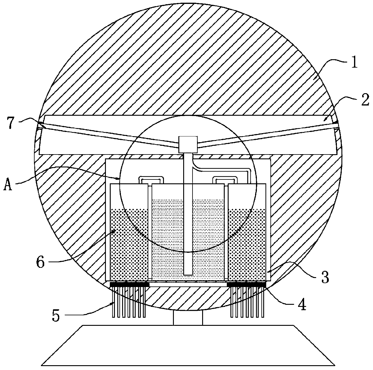
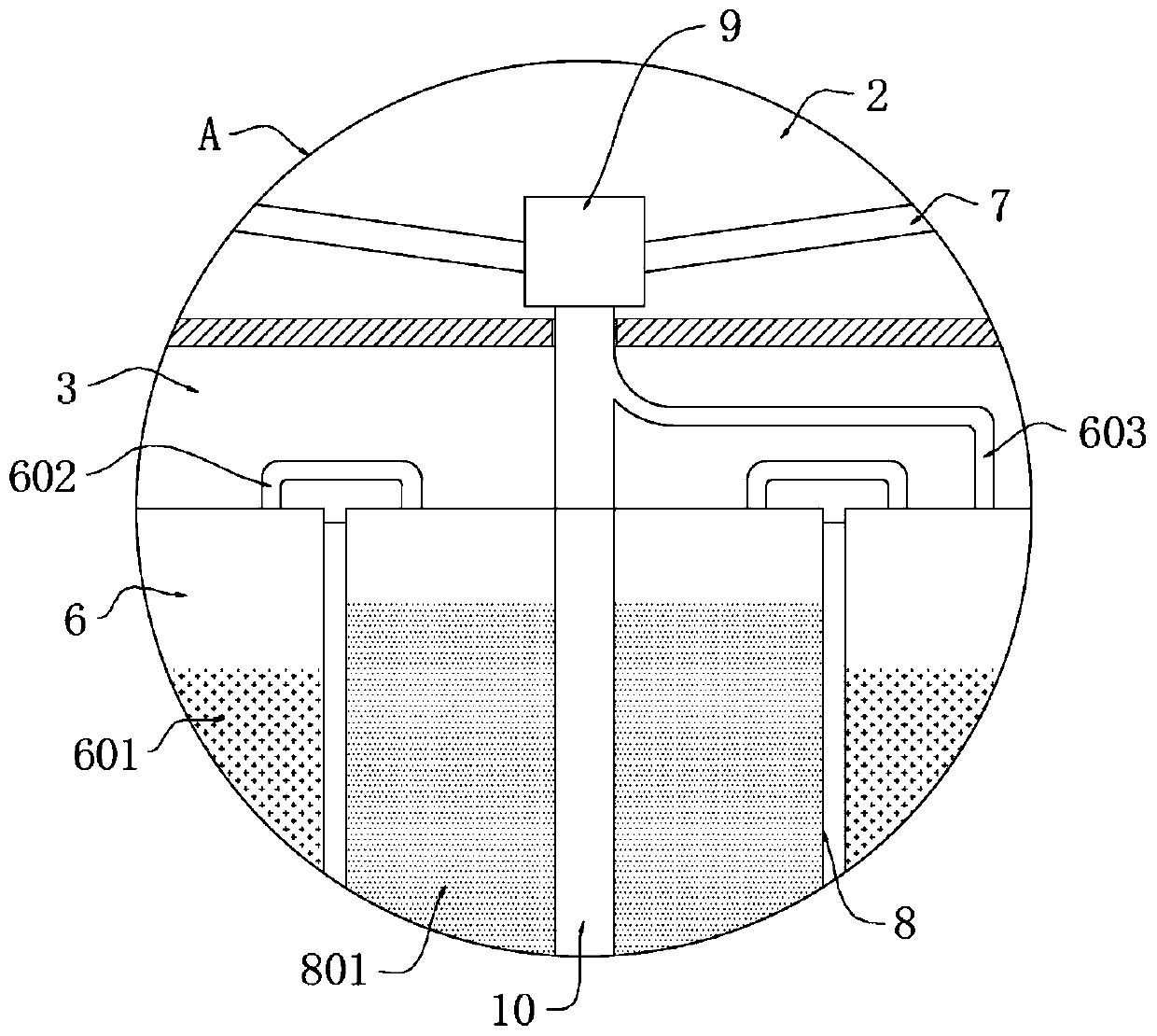
[0031] refer to Figure 1-3 , a ball type self-induction self-rotating fire extinguishing device, comprising a sphere 1, a tube cavity 2 and a storage cavity 3 respectively opened in the sphere 1, an annular heat conducting plate 4 is embedded in the bottom of the storage cavity 3, and the upper end of the annular heat conducting plate 4 An annular high-pressure tank 6 is installed, and a material storage tank 8 is installed in the center of the storage cavity 3, and the material storage tank 8 is located in the middle of the annular high-pressure tank 6, and the upper ends of the material storage tank 8 and the annular high-pressure tank 6 are symmetrically installed with multiple The pressure pipe 602, the annular high-pressure tank 6 is filled with evaporating liquid 601, the storage tank 8 is filled with metal powder 801, and the powder discharge pipe 10 is sealed and inserted on the storage tank 8, and the upper end of the powder discharge pipe 10 extends to the tube A pr...

Embodiment 2

[0042] refer to Figure 4 , a ball-type self-induction self-rotating fire extinguishing device, which is basically the same as Embodiment 1, the difference is that:

[0043] A fixed frame 101 is installed on the inner wall of the lower end of the powder discharge pipe 10, and a rotating shaft 102 is inserted into the fixed frame 101 for rotation. ;

[0044] The upper end of the powder discharge pipe 10 generates negative pressure so that the direction of the airflow flows from bottom to top, and the flowing airflow passes through the diversion groove 104 to make the diversion cone 103 rotate, and the rotating diversion cone 103 loosens the surrounding copper powder, making it easier for the copper powder to The copper powder is extracted, and the copper powder flows along the diversion groove 104 and the air flow at the same time, so that the copper powder is extracted more uniformly, and the ejected copper powder covers the fire area more uniformly, increasing the effect of ...


PUM


Abstract

The invention discloses a ball type self-induction self-rotation fire extinguishing device. The ball type self-induction self-rotation fire extinguishing device comprises a ball body, and a pipe cavity and a storage cavity are separately formed in the ball body. An annular heat conducting plate is embedded at the bottom of the storage cavity, and an annular high-pressure tank is installed at the upper end of the annular heat conducting plate. A storage tank is installed in the center of the storage cavity, and the storage tank is located in the middle of the annular high-pressure tank. A plurality of pressure equalizing pipes are symmetrically arranged at the upper ends of the storage tank and the annular high-pressure tank together. The annular high-pressure tank is filled with evaporating liquid, and the storage tank is filled with metal powder. A powder discharge pipe is hermetically inserted into the storage tank, and the upper end of the powder discharge pipe extends into the pipecavity and is provided with a pressure valve. According to the ball type self-induction self-rotation fire extinguishing device, a fire can be automatically detected and extinguished through annularheat conducting sheets and the annular heat conducting plate; harmless and environmental-friendly fire extinguishing can be realized through copper powder; the ball body is made to rotate through an arc spray pipe, and the fire extinguishing range is enlarged; and fire extinguishing is more uniform through a guide cone, the fire extinguishing effect is enhanced, and reburning is prevented.

Description

technical field [0001] The invention relates to the field of fire safety, in particular to a ball-type self-induction self-rotating fire extinguishing device. Background technique [0002] In some archives, libraries and other areas, it is necessary to strictly control the source of fire to avoid irreparable losses caused by fire in these places. Cause secondary damage. [0003] Existing fire extinguishers in libraries, archives and other areas are usually carbon dioxide fire extinguishers. The storage conditions of carbon dioxide fire extinguishers are relatively high, and carbon dioxide is driven upward by the hot air after a large amount of carbon dioxide gas is extinguished during fire extinguishing, making firefighters prone to suffocation If there is a danger, the fire extinguishing effect of carbon dioxide in a place with a large space and good air circulation is poor, and the existing fire extinguishing devices are usually hand-held or cart-type, which require manua...

Claims


Application Information

Patent Timeline
Patent Type & Authority Applications(China)
IPC IPC(8): A62C31/00A62C31/28A62C37/36
CPCA62C31/00A62C31/28A62C37/36
Inventor 蔡坤杰
Owner 朱香芽
Why Eureka
Try Eureka