Switch cabinet with automatic fire extinguishing function

An automatic fire extinguishing and switchgear technology, applied in the field of switchgear, can solve the problems of switchgear fire, large weight and volume, safety accidents, etc., to achieve the effect of convenient maintenance and replacement, avoiding fire expansion, and increasing fire extinguishing effect

Active Publication Date: 2021-03-26
东营金丰正阳科技发展有限公司
View PDF17 Cites 4 Cited by
  • Summary
  • Abstract
  • Description
  • Claims
  • Application Information

AI Technical Summary

Problems solved by technology

[0005] The purpose of the present invention is to provide a switchgear with automatic fire extinguishing function, to solve the fire inside the switchgear proposed in the above background technology, if it is not handled in time, it will bring serious safety accidents; It is difficult to overhaul the electrical equipment inside the switchgear; in addition, it may be necessary to move the switchgear during the maintenance process. Since there are a large number of electrical equipment inside the switchgear, its weight and volume are relatively large, and it is difficult to rely on manpower to move

Method used


Image

  • Switch cabinet with automatic fire extinguishing function
  • Switch cabinet with automatic fire extinguishing function
  • Switch cabinet with automatic fire extinguishing function

Examples


Embodiment 1

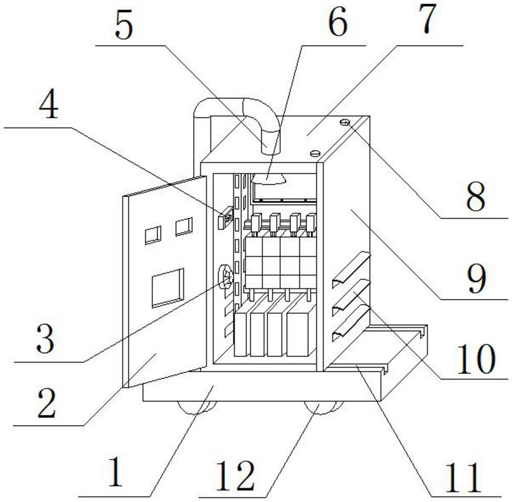
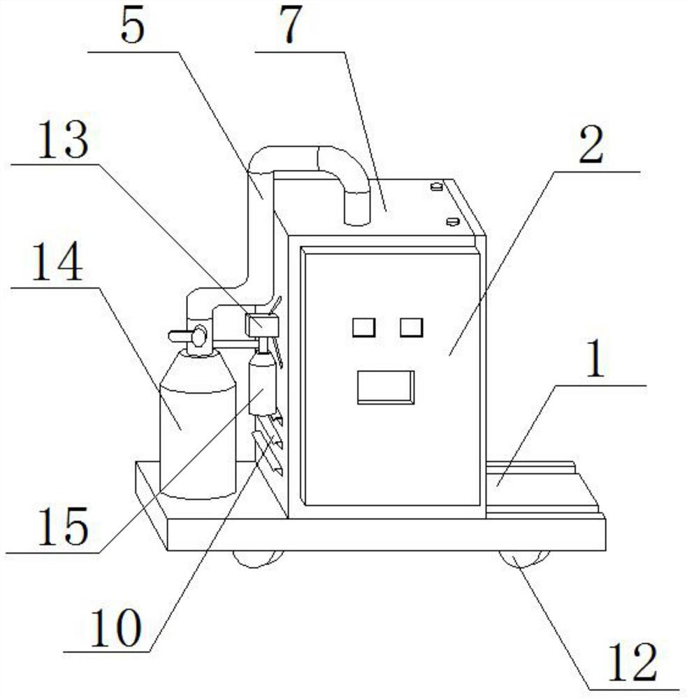
[0032] see Figure 1-Figure 7 , the present invention provides a switchgear with automatic fire extinguishing function, comprising a base 1, a cabinet body 7 is fixedly installed above the base 1, a cabinet door 2 is movably installed on the left end of the cabinet body 7, and smoke is fixedly installed inside the cabinet body 7 Sensor 3, a temperature sensor 4 is fixedly installed above the smoke sensor 3, a nozzle 6 is fixedly installed above the temperature sensor 4, a connecting pipe 5 is fixedly installed above the nozzle 6, and a bolt 8 is movably installed on the right side of the connecting pipe 5. The right side of the body 7 is movably equipped with a movable plate 9, the lower end of the movable plate 9 is movably installed with a wind deflector 10, the upper surface of the base 1 is provided with a chute 11, and the bottom of the base 1 is movably equipped with wheels 12, and the cabinet body 7 A solenoid valve 13 is fixedly installed on the left side, a starter bo...

Embodiment 2

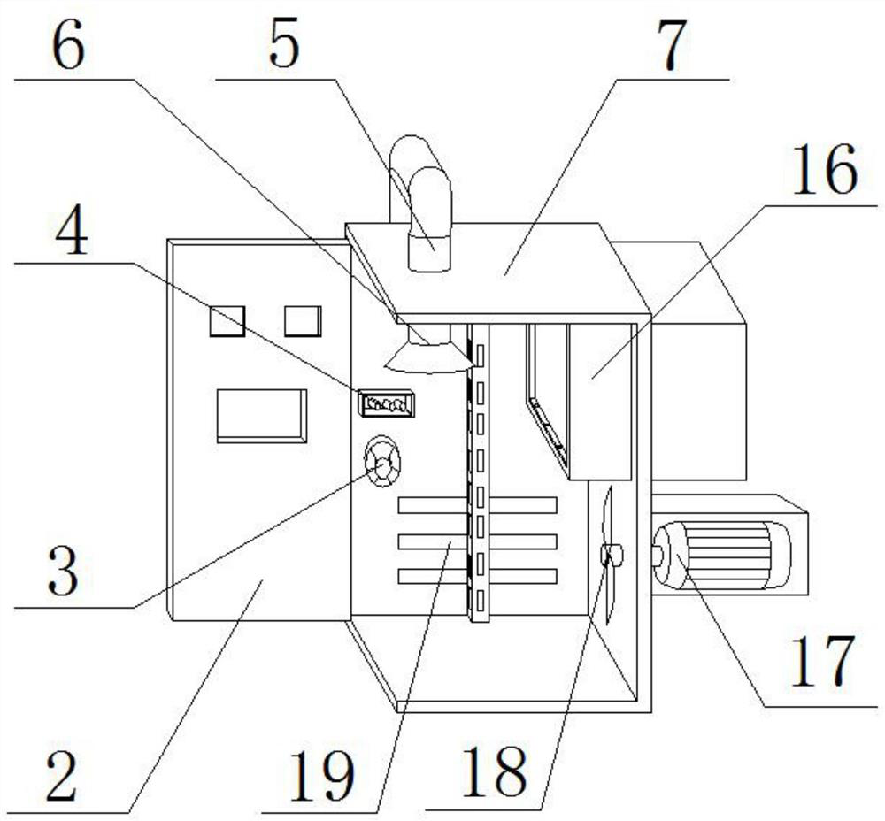
[0036] like Figure 1-5 As shown, the difference between this embodiment and Embodiment 1 is that the connecting pipe 5 runs through the upper surface of the cabinet body 7, one end of the connecting pipe 5 is connected with the nozzle 6, and the other end of the connecting pipe 5 is connected with the gas storage The bottles 14 are connected, the smoke sensor 3 and the temperature sensor 4 are connected with the electromagnetic valve 13 by wires, the dry powder box 16 runs through the rear surface of the cabinet 7, the sealing plate 20 and the dry powder box 16 are connected by a rotating shaft, and the expansion metal One end of the block 23 is fixedly installed in the inside of the fixing hole 22, and the other end of the expansion metal block 23 is fixedly installed in the inside of the fixing box 24, and the fixing pin 21 and the dry powder box 16 are fixedly connected through the fixing hole 22; the ventilation holes 19 are provided in total There are six groups, wherein...

Embodiment 3

[0039] like figure 1 and Figure 7 As shown, the difference between this embodiment and Embodiments 1 and 2 is that there are three groups of fixing grooves 32, wherein two groups of fixing grooves 32 are respectively provided at the upper and lower ends of the right surface of the cabinet body 7, and the other group Fixed groove 32 is offered at the right surface rear end of cabinet body 7, and fixed bar 33 is provided with three groups altogether, wherein two groups of fixed bars 33 are fixedly installed on the upper and lower ends of the left surface of movable plate 9, and another group of fixed bars 33 are fixedly installed on movable plate 9. On the rear end of the left surface of the plate 9, several groups of threaded holes 31 are arranged, and several groups of threaded holes 31 are evenly opened on the fixing groove 32 and the fixing bar 33, and a group of bolts 8 are movably installed on each group of threaded holes 31, and the cabinet body 7 and movable plate 9 ar...


PUM


Abstract

The invention discloses a switch cabinet with an automatic fire extinguishing function. The switch cabinet comprises a base, wherein a cabinet body is fixedly arranged above the base, a cabinet door is movably arranged at the left end of the cabinet body, and a smoke sensor and a temperature sensor are arranged in the cabinet body. The occurrence of a fire can be detected by the sensors, when thefire occurs, a starting bottle can be opened through using an electromagnetic valve, and finally a gas storage bottle releases a dry ice fire extinguishing agent, so that the fire extinguishing effectis achieved; in order to avoid the failure of the sensor or the electromagnetic valve and the starting bottle, a dry powder box is arranged on the cabinet body, so that the temperature in the cabinetbody can be rapidly increased in case of fire, an expansion metal block can be heated to expand, a fixing pins are ejected out of a fixing hole by a pushing force generated by expansion, and finallya sealing plate can be ejected open by a spring telescopic rod, so that the purpose of opening the dry powder box is achieved, dry powder comes out of the dry powder box, the purpose of fire extinguishment can be achieved, double fire extinguishment guarantees are achieved, and fire spreading can be effectively avoided.

Description

technical field [0001] The invention belongs to the technical field of switch cabinets, and in particular relates to a switch cabinet with an automatic fire extinguishing function. Background technique [0002] The switch cabinet is a kind of electrical equipment. The outside line of the switch cabinet first enters the main control switch in the cabinet, and then enters the sub-control switch. Each branch is set according to its needs. The main function of the switch cabinet is to generate, transmit, distribute and In the process of electric energy conversion, open and close, control and protect electrical equipment. The components in the switch cabinet are mainly composed of circuit breakers, isolating switches, load switches, operating mechanisms, transformers and various protection devices. They are mainly suitable for power generation. Plants, substations, petrochemical, metallurgical rolling, light industry textiles, factories and mines, residential quarters, high-rise ...

Claims


Application Information

Patent Timeline
Patent Type & Authority Applications(China)
IPC IPC(8): H02B1/28H02B1/56H02B1/52H02B1/50H02B1/30H02B1/32A62C3/16A62C31/02A62C37/36G08B17/10
CPCH02B1/28H02B1/56H02B1/52H02B1/50H02B1/306H02B1/303H02B1/32A62C3/16A62C31/02A62C37/36G08B17/10
Inventor 不公告发明人
Owner 东营金丰正阳科技发展有限公司
Why Eureka
Try Eureka