Automated hand

a hand and hand technology, applied in the field of automatic hands, can solve the problems of unnatural hand, many hands are necessarily large and bulky, and the hand is not natural, and achieve the effect of reducing the lateral movement of the thumb

Active Publication Date: 2018-02-08
5TH ELEMENT
View PDF3 Cites 23 Cited by
  • Summary
  • Abstract
  • Description
  • Claims
  • Application Information

AI Technical Summary

Benefits of technology

[0034]According to a further aspect, the invention provides an automated hand comprising: a palm; and two or more digits extending from the palm; wherein at least one digit forms a thumb mounted at or near a first side of the palm of the hand, wherein the thumb substantially opposes at least one other digit and wherein the hand comprises a compressible thumb cushion positioned in contact with a portion of the thumb. The compressible thumb cushion may be configured to dampen lateral movement of the thumb under a lateral impact and to provide grip compliance.

Problems solved by technology

However, conventional automated hands have several disadvantages.
Many of the hands are necessarily large and bulky to fit the working parts within the hand.
This can result in the hand looking unnatural.
Conventional automated hands are typically unable to flex and curve around an object to grip the object reliably.
This is particularly problematic where the object is curved or slippery, such as a drinking glass or bottle.
The motors of known automated hands may also strain to provide an adequate grip and therefore wear quickly.
Further, because these hands do not curve and flex, the hands can also feel unnatural in a handshake.
Another problem with known automated hands is that the hands themselves are not waterproof.
When the motors of the hand drive the fingers to a non-biased position, the resistance from the springs causes the fingers to move more slowly than desired and may strain the drive motors and drain the battery power quickly.
Some designs include one directional clutches to absorb impact forces but these do not protect against impacts in the opposite direction.
This arrangement increases the mass that must be moved when moving a digit, requires wiring along the digits and restricts the space available for linkages.
Due to the confined space it is very difficult to accommodate clutch mechanisms.
The motors and working parts of known automated hands are also susceptible to damage when digits of the hands are subjected to too much tension or to an end impact.
Conventional automated hands may provide a wrist positioning system, but these systems are typically complex, large and cumbersome, which extends the palm away from the arm creating an extended, heavy, ungainly and unnatural looking wrist.
In addition, there are limited ways in which the hand can move in relation to the wrist and the wrist is typically not fluid compatible.
Although it is known for automated hands to be used as training hands for new hand amputees, these hands do not provide an indication that EMG (electromyography) signals have been received by the user and / or which grip has been selected.
Consequently, hand amputees may find it frustrating to become accustomed to the EMG algorithms needed to change the grip patterns of the hand, especially when they cannot tell which grip pattern has been selected or whether EMG signals are being received.
A significant disadvantage of known automated hands is that the working parts, especially the electronics, are sensitive to getting wet.
Consequently, the naked hands cannot be used in a wet environment, such as in a bath, shower, or when washing dishes, without becoming damaged.
This can be frustrating for a user because it is difficult to place a glove over a prosthetic hand.
The gloves may also wear and tear easily.
Grip surfaces on automated hands may also suffer from excessive wear if contact surfaces are formed of a material that is too soft and may not provide suitable grip if the material is hard wearing and formed of as hard material.

Method used


Image

  • Automated hand
  • Automated hand
  • Automated hand

Examples


first exemplary embodiment

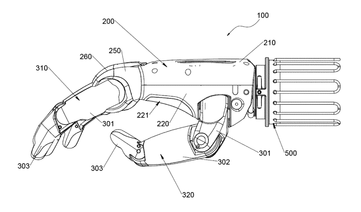
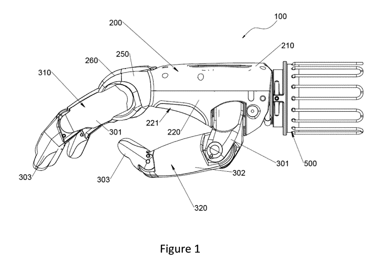
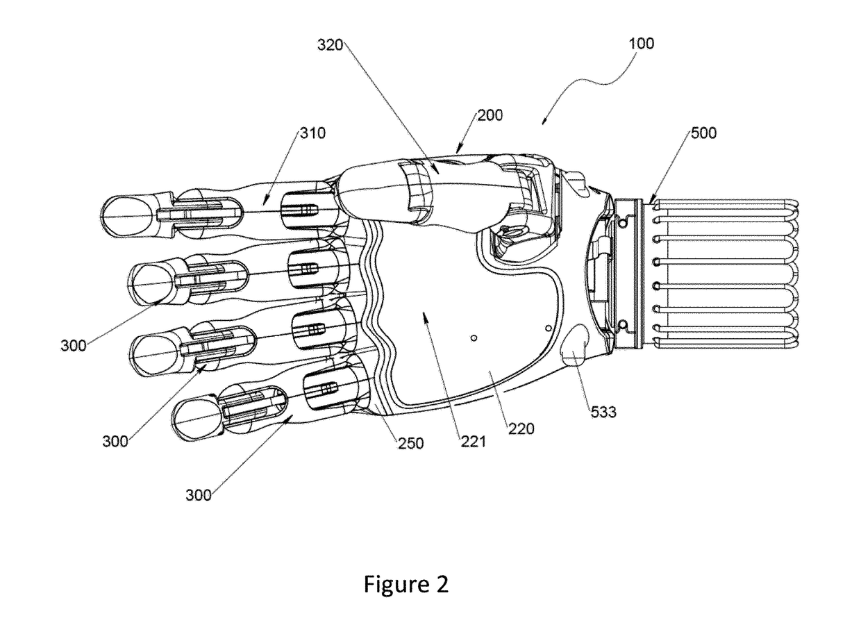
[0171]The automated hand 100 of the first exemplary embodiment is shown in FIGS. 1 to 25 and comprises a palm 200 and two or more digits 300 extending from the palm 200. Each digit may be attached to the palm by a knuckle joint. The digits are configured to move between an open, substantially flexed (extended) position, and a substantially closed, gripping position. A digit 300 may be in the form of a finger 310 or thumb 320. In one example, the hand 100 may comprise two digits 300, one being a finger 310 and the other being a substantially opposing thumb 320. In another form, the hand 100 may comprise four or more fingers 310 and a substantially opposing thumb 320. In yet another form, the hand 100 may comprise only two or more fingers 310. It is envisaged that in yet another form, the hand 100 may comprise one or more fingers 310 and two or more thumbs 320, although this is not a preferred embodiment because it is an unnatural looking hand.

[0172]The hand 100 of the invention also ...

second exemplary embodiment

[0416]FIGS. 26 to 66 show an automated hand according to a second embodiment employing a different thumb rotation locking mechanism, wrist locking mechanism, overload knuckle clutch, removable grip plates and related features.

[0417]Those parts that are equivalent to corresponding parts in the first embodiment have been given the same numbering and the above description should be referenced in relation to those parts. The metacarpal brace has the same properties described in relation to the previous exemplary embodiment. The actuator described below includes a connector housing the actuator although a connector need not necessarily house an actuator in alternate embodiments.

Thumb Rotation Locking

[0418]Referring now to FIGS. 26 to 30 an alternate thumb design is shown. Thumb 701 has an actuator 702 provided at its proximal end (including the actuator housing) which is also its point of attachment to palm 704. A resilient mount 703 is mounted to palm 704 and includes a cavity dimension...


PUM

PropertyMeasurementUnit
temperatureaaaaaaaaaa
angular rotationaaaaaaaaaa
forceaaaaaaaaaa

Abstract

The invention relates to an automated hand, such as a prosthetic hand. In one form, the automated hand may be fluid compatible. In one form, the automated hand may comprise features to reduce the risk of harm to motors and/or other sensitive components of the hand when subject to an impact. In one form, the hand may comprise a wrist joint configured to allow the hand to curl and flex and/or to rotate. In one form, one or more digits of the hand may be individually controlled. In one form the hand may include a thumb rotation locking mechanism. In one form the hand may be provided with removable grip plates. In one form, the hand may be configured for use as a training hand.

Description

RELATED APPLICATIONS[0001]This application is a Continuation-in-Part of U.S. Ser. No. 14 / 420,706, filed 15 Feb. 2015, which is a National Stage of PCT / NZ2013 / 000140, filed 12 Aug. 2013, which claims benefit of U.S. Provisional Ser. No. 61 / 682,291, filed 12 Aug. 2012, and which applications are incorporated herein by reference in their entireties. For convenience, a copy of U.S. Ser. No. 14 / 420,706 is attached hereto at Appendix A.[0002]This application is a Continuation-in-Part of PCT / NZ2016 / 050163, filed 5 Oct. 2016, which claims benefit of U.S. Provisional Ser. No. 62 / 237,089, filed 5 Oct. 2015 and NZ Application No. 722088, filed 12 Jul. 2016, and which applications are incorporated herein by reference in their entireties.[0003]To the extent appropriate, a claim of priority is made to each of the above disclosed applications.TECHNICAL FIELD[0004]The invention relates to an automated hand, such as a prosthetic hand, and components for an automated hand.BACKGROUND OF THE INVENTION[...

Claims


Application Information

Patent Timeline
Patent Type & Authority Applications(United States)
IPC IPC(8): A61F2/58A61L27/04A61L27/56A61F2/68A61L27/16
CPCA61F2/586A61F2/68A61L27/165A61L27/56A61L27/04A61F2002/704A61F2002/5003A61F2002/5007A61F2002/5038A61F2/583B25J15/0009A61F2002/5079A61F2002/587A61F2002/701
Inventor JURY, MATHEW JAMESLOVEGROVE, DAVID NEILDAWSON, ROSS HUGHANJACKSON-HILL, OLIVER CHARLES GRAHAMBEST, DARRYL JOHNLOWY, JONATHAN DAVID
Owner 5TH ELEMENT
Why Eureka
Try Eureka