Systems and methods for thermally actuated flow control

a flow control and thermal actuator technology, applied in the direction of valve operating means/release devices, process and machine control, instruments, etc., can solve the problems of loss of degrees of freedom, reduced control efficiency, and reduced reaction rate-limited process, so as to reduce the heat generation rate and increase the deflection

Active Publication Date: 2018-02-08
BOARD OF RGT THE UNIV OF TEXAS SYST
View PDF12 Cites 17 Cited by
  • Summary
  • Abstract
  • Description
  • Claims
  • Application Information

AI Technical Summary

Benefits of technology

[0016]Various implementations provide an inherently safer design feature for microchannel reactors that provides temperature control at the individual channel level. Bimetallic strips are installed within the combustion channel to regulate fluid flow in the channel, forming a thermally-actuated “valve”. Bimetallic strips convert a temperature change into a mechanical displacement. Heating the strip increases its deflection from a wall and thereby restricts but does not completely block flow in the combustion channels, which consequently reduces the rate of heat generation, according to some implementations. In other implementations, the thermally-actuated valve may be used in other structures for which thermally actuated flow control is desired.

Problems solved by technology

Reduced geometric dimensions of the flow channels (typically on the order of millimeters) increase the surface-area-to-volume ratio and minimize transport limitations, resulting in a much faster, reaction rate-limited process.
The capital and operating cost savings associated with microchannel reactors come at the price of several control challenges.
The combination of unit operations (heat exchange, reaction, fluid flow) in a single device results in a loss of degrees of freedom.
Additionally, reduced dimensions make it difficult to incorporate distributed sensors and actuators, thus limiting the control of such reactors to a boundary approach based on sensing and adjusting the channel output and, respectively, input properties.
While autothermal designs avoid the need for an external heating medium, they can be more challenging to operate.
Improper alignment (in the axial dimension) of heat fluxes can result in the formation of hotspots (if local heat generation exceeds consumption) or reactor extinction.
However, very few studies have focused on the dynamic challenges associated with the operation of microchannel reactors.

Method used


Image

  • Systems and methods for thermally actuated flow control
  • Systems and methods for thermally actuated flow control
  • Systems and methods for thermally actuated flow control

Examples


Embodiment Construction

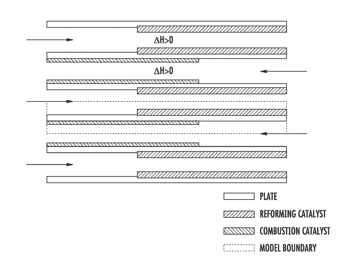
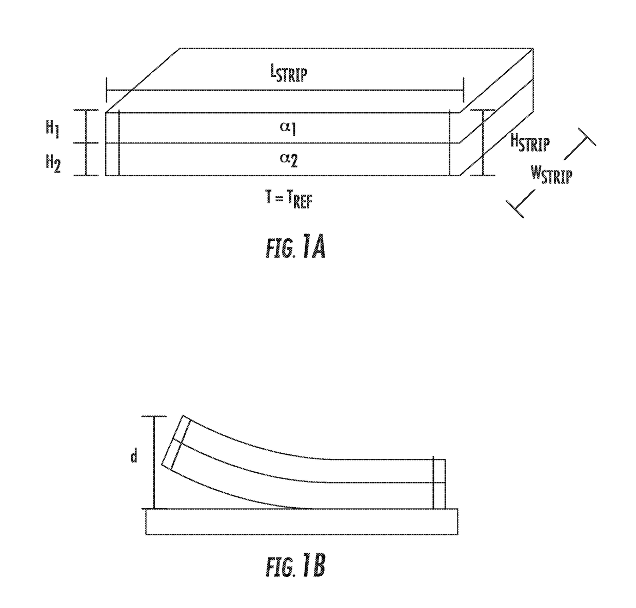
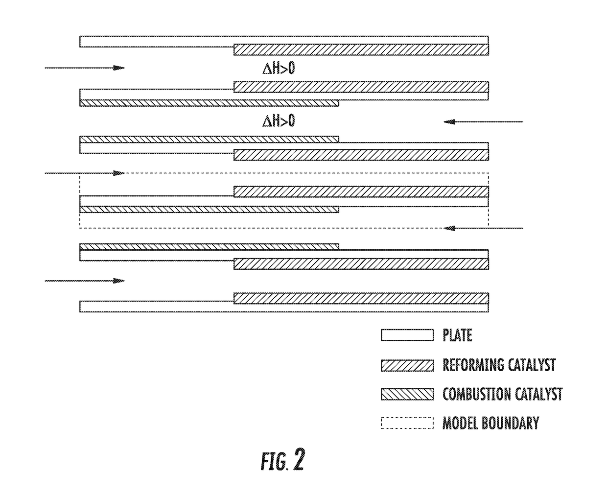
[0045]Various implementations provide an inherently safer design feature for microchannel reactors that provides temperature control at the individual channel level. This approach relies on bimetallic strips embedded within the combustion channel, forming a thermally-actuated “valve”. Bimetallic strips convert a temperature change into a mechanical displacement. Heating the strip increases its deflection and thereby restricts but does not completely block flow in the combustion channels of the reactor, which consequently reduces the rate of heat generation according to some implementations. The thermally-actuated valve is not limited to use in microchannel reactors and may be used in other structures for which thermally actuated flow control is desired, according to some implementations.

[0046]FIGS. 3 through 5C illustrate a thermally actuated flow control system 10 according to one implementation. The system includes a first linear array of bimetallic strips 12 disposed on an upper ...


PUM


Abstract

Various implementations provide an inherently safer design feature for microchannel reactors that provides temperature control at the individual channel level. This approach relies on bimetallic strips embedded within the combustion channel, forming a thermally-actuated “valve”. Bimetallic strips convert a temperature change into a mechanical displacement. Heating the strip increases its deflection and thereby restricts flow in the combustion channels, which consequently reduces the rate of heat generation. The thermally-actuated valve is not limited to use in microchannel reactors and may be used in other structures for which thermally actuated flow control is desired, according to some implementations.

Description

CROSS REFERENCE TO RELATED APPLICATION[0001]This application claims priority to U.S. Provisional Patent Application No. 62 / 126,878 entitled “Systems and Methods for Thermally Actuated Flow Control,” filed Mar. 2, 2015, the content of which is herein incorporated by reference in its entirety.BACKGROUND[0002]Microchannel reactors are one of the most successful implementations of the process intensification concept. Reduced geometric dimensions of the flow channels (typically on the order of millimeters) increase the surface-area-to-volume ratio and minimize transport limitations, resulting in a much faster, reaction rate-limited process. Equipment sizes of intensified processes using microchannel reactors are at least one order of magnitude smaller than conventional devices of equivalent capacity, and consequently result in significant capital savings. Additionally, reduced holdups improve process safety and efficiency and make the process more agile. Microchannel reactors have found ...

Claims


Application Information

Patent Timeline
Patent Type & Authority Applications(United States)
IPC IPC(8): F16K99/00B01J19/00G05D23/185
CPCF16K99/0036F16K99/0026G05D23/1854B01J19/0093B01J2219/00783B01J2219/00792B01J2219/00822B01J2219/00873B01J2219/0095B01J2219/00835B01J2219/00855B01J2219/0086B01J2219/00876F16K31/002B01J19/0046F16K17/38G05D23/00G05D23/08
Inventor BALDEA, MICHAELPATTISON, RICHARDDONAHUE, MELISSAGUPTA, AKASH
Owner BOARD OF RGT THE UNIV OF TEXAS SYST
Why Eureka
Try Eureka