
Device and method to measure ventricular arterial coupling and vascular performance

a technology of ventricular arterial coupling and measuring device, applied in the field of hospital management, can solve the problems of not yet replacing pacs, inability to directly measure sv, and inability to meet patient expectations

Active Publication Date: 2018-02-15
THE JOHN HOPKINS UNIV SCHOOL OF MEDICINE
View PDF0 Cites 10 Cited by
  • Summary
  • Abstract
  • Description
  • Claims
  • Application Information

AI Technical Summary

Benefits of technology

The patent describes a device and method for measuring the coupling between a person's ventricle and their artery. This is done by measuring the time it takes for a pulse wave to travel from the ventricle to different locations in the body. By measuring the difference in this time between the different locations, the device can determine how well the coupling is going. This can be useful in diagnosing and treating various health issues related to blood flow. The device is easy to use and provides accurate results.

Problems solved by technology

However, these parameters are not able to directly measure SV and, hence, CO.
Although the pulmonary artery catheter (PAC) is still considered the gold standard to monitor SV and CO, its invasive nature and potential for life-threatening complications largely restrict its use in the modern era.
However, they have not yet replaced PACs due to poor trending ability and inadequate agreement with the clinical standard (e.g., PAC).
While ultrasound-based techniques have a number of advantages, they have several important limitations, such as the difficulty of continuous real-time monitoring, interference from electric cautery, and operator dependence.
Moreover, TEE is an invasive technique and is poorly tolerated by un-sedated patients.
In addition, another drawback of TEE compared to pulmonary artery catheters is the inability to measure real-time SV and CO.
There have been reports of continuous CO measurements based on pulse transit time, which is inexpensive and easy to use but showed poor agreement with gold standard.

Method used


Image

  • Device and method to measure ventricular arterial coupling and vascular performance
  • Device and method to measure ventricular arterial coupling and vascular performance
  • Device and method to measure ventricular arterial coupling and vascular performance

Examples


Embodiment Construction

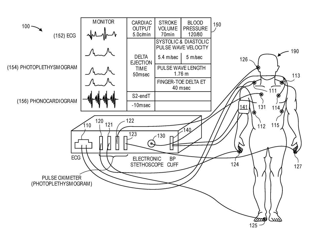
[0023]The presently disclosed subject matter now will be described more fully hereinafter with reference to the accompanying Drawings, in which some, but not all embodiments of the inventions are shown. Like numbers refer to like elements throughout. The presently disclosed subject matter may be embodied in many different forms and should not be construed as limited to the embodiments set forth herein; rather, these embodiments are provided so that this disclosure will satisfy applicable legal requirements. Indeed, many modifications and other embodiments of the presently disclosed subject matter set forth herein will come to mind to one skilled in the art to which the presently disclosed subject matter pertains having the benefit of the teachings presented in the foregoing descriptions and the associated Drawings. Therefore, it is to be understood that the presently disclosed subject matter is not to be limited to the specific embodiments disclosed and that modifications and other ...


PUM


Abstract

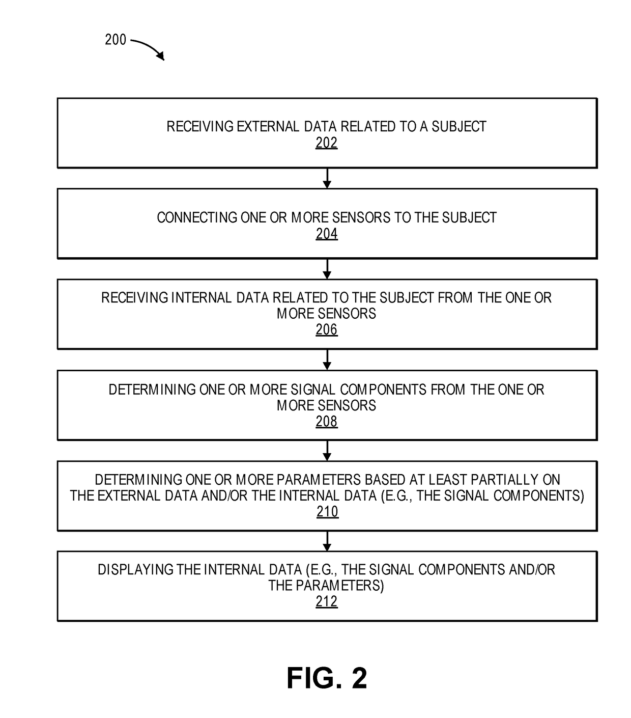
A device for measuring a ventricular-arterial coupling of a subject includes first and second inputs. The first input receives signals from a plurality of electrocardiogram sensors that are coupled to the subject at a plurality of first locations. The second input receives signals from a plurality of photoplethysmogram sensors that are coupled to the subject at a plurality of second locations. The second locations are selected from the group consisting of a head of the subject, an arm of the subject, and a leg of the subject. The signals received from the electrocardiogram sensors and the signals received from the photoplethysmogram sensors are received simultaneously. The device also includes a monitor configured to display the signals from the electrocardiogram sensors and the signals from the photoplethysmogram sensors.

Description

CROSS-REFERENCE TO RELATED APPLICATIONS[0001]The present application is a continuation-in-part of U.S. patent application Ser. No. 15 / 449,410, filed on Mar. 3, 2017, which claims priority to U.S. Provisional Patent Application No. 62 / 302,884, filed on Mar. 3, 2016, each of which is hereby incorporated by reference in its entirety.FIELD OF THE INVENTION[0002]The present invention relates generally to hospital management. More particularly, the present invention relates to emergency and operating room management to support an objective triage evaluation.BACKGROUND OF THE INVENTION[0003]In clinical practice, hemodynamic monitoring during anesthesia and in intensive care units is often employed. The goal of hemodynamic monitoring is to guide interventions as well as to ensure adequate end organ perfusion and oxygen delivery by optimizing stroke volume (SV) and cardiac output (CO). Conventional hemodynamic variables such as arterial blood pressure, central venous pressure, and urine outp...

Claims


Application Information

Patent Timeline
IPC IPC(8): A61B5/02A61B5/0295A61B5/024A61B8/00A61B8/06A61B7/04A61B5/00A61B8/08A61B5/026A61B5/044A61B5/352
CPCA61B5/02028A61B5/0261A61B5/0295A61B5/02416A61B5/044A61B8/065A61B7/04A61B5/02007A61B5/6815A61B5/6823A61B5/6824A61B5/6826A61B5/6828A61B8/488A61B8/463A61B5/6829A61B7/00A61B5/0205A61B5/021A61B5/02125A61B5/029A61B5/082A61B2562/04A61B5/352A61B5/026A61B5/742A61B5/339A61B5/349
Inventor BARODKA, VIACHASLAUOBATA, YURIE
Owner THE JOHN HOPKINS UNIV SCHOOL OF MEDICINE
Learn More