
Downhole monitoring device arranged in-line with a sucker rod string

a monitoring device and sucker rod technology, applied in the field of monitoring devices, can solve the problems of no system available that can directly measure, no well operator can verify the assumptions used in vertical well cases, and the production rate is being reduced, so as to increase the time between workovers and optimize production

Inactive Publication Date: 2018-02-15
WELL INNOVATION
View PDF30 Cites 7 Cited by
  • Summary
  • Abstract
  • Description
  • Claims
  • Application Information

AI Technical Summary

Benefits of technology

The purpose of the device described in this patent is to improve the production of oil from wells that are not perfectly straight. The device helps to prolong the time between when the well needs to be worked on again, which is a costly and time-consuming process.

Problems solved by technology

Today there is no system available that can directly measure the downhole behaviour of sucker rod(s) and pump connected to a surface pump jack system in either vertical, deviated and / or horizontal well(s).
This, for the most part, may have been a valid assumption for a vertical well or at least accepted by well operators, but as more and more wells are being drilled directionally, the assumptions used for the vertical well cases are being questioned by the well operator as no longer valid.
This lack of data has resulted in lower production rates and an increase in workovers frequency due to the lack of downhole measurement associated with the increase in friction and drag resulting from the increase in well deviation.
This lack of information on the rod system's behaviour downhole has resulted in increasing stresses in the rods, resulting in a higher frequency of workovers.
This is a costly process during which the well's production must be shut-in for longer periods.
Today it is estimated that production rates are lower than expected due to not knowing what is happening downhole.

Method used


Image

  • Downhole monitoring device arranged in-line with a sucker rod string
  • Downhole monitoring device arranged in-line with a sucker rod string
  • Downhole monitoring device arranged in-line with a sucker rod string

Examples


first embodiment

of the Present Invention

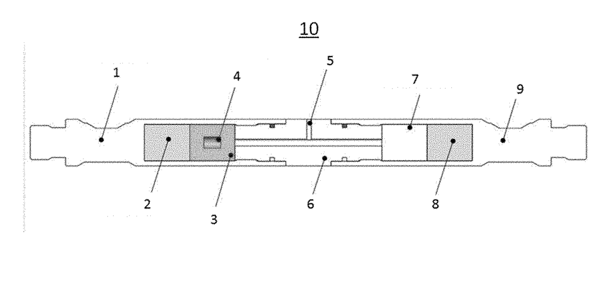
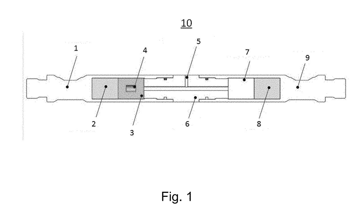
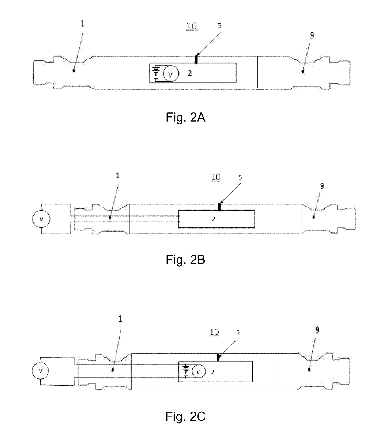
[0037]Reference is made to FIG. 1. FIG. 1 shows a block diagram of the monitoring device 10 which can be arranged anywhere in-line in the sucker rod string with the correct crossovers. The monitoring device includes a top sub portion 1, a bottom sub portion 9, and an intermediate main sub portion 6 in between. The monitoring device 10 comprises inside a power supply 2, electronics 3, accelerometer 4, communication port 5, strain gauges7 and a Pressure Temperature (PT) sensor 8. The top 1 and bottom 9 subs of the monitoring device 10 are threaded, so that they can be screwed in-line with the mating sucker rod threads. The connections between the top sub 1, the middle sub 6 and the bottom sub 9 within the monitoring device 10 itself can be threaded, but it should be made allowances for torque, so a locking system for the middle 6 to the bottom 9 sub can be used, in order not to affect the calibration values. Another locking system for the top 1 to the middle 6 ...


PUM


Abstract

The present invention concerns a downhole logging tool adapted to be arranged in-line in a sucker rod string. The tool is adapted for monitoring and performing at least one of: logging tension / compression, torque, temperature, pressure, and position (acceleration), for the purpose of optimizing (oil)well production and identifying downhole mechanical problems. The tool can be utilized in vertical, deviated and / or horizontal wells. Multiple monitoring tools can be installed in the sucker rod system in order to detect wear issues.

Description

TECHNICAL FIELD[0001]The present invention relates to at least one monitoring device that is adapted to be arranged in-line with a sucker rod string.BACKGROUND ART[0002]Today there is no system available that can directly measure the downhole behaviour of sucker rod(s) and pump connected to a surface pump jack system in either vertical, deviated and / or horizontal well(s). This, up until 15 years ago had not been an issue, because most wells were drilled vertically and it was assumed that the surface movement was directly representative of the downhole movement. This, for the most part, may have been a valid assumption for a vertical well or at least accepted by well operators, but as more and more wells are being drilled directionally, the assumptions used for the vertical well cases are being questioned by the well operator as no longer valid. Today the well operator is modelling the pump jack motion at surface based on the out-of-date vertical models and / or some limited research d...

Claims


Application Information

Patent Timeline
Patent Type & Authority Applications(United States)
IPC IPC(8): E21B47/00G01V11/00E21B47/06E21B17/00E21B43/12
CPCE21B47/0008E21B17/00E21B43/126E21B2043/125E21B47/065E21B47/00G01V11/002E21B47/06E21B47/009E21B47/07E21B43/127
Inventor SUERMONDT, RUTGERSLOTTEROY, STIANPALUCH, PRZEMYSLAW TOMASZMACKAY, JOHNROED, KIMKJERLAND, TRONDTVEIT, TROND ARILDHANSSEN, KRISTER BERVEN
Owner WELL INNOVATION
Learn More