
Mechanically driven air vehicle thermal management device

a technology of thermal management device and mechanical drive, which is applied in the direction of machines/engines, liquid fuel engines, lighting and heating apparatus, etc., can solve the problems of reducing the efficiency of the system, and wasting a large amount of useful energy

Active Publication Date: 2018-02-15
GENERAL ELECTRIC CO
View PDF6 Cites 28 Cited by
  • Summary
  • Abstract
  • Description
  • Claims
  • Application Information

AI Technical Summary

Benefits of technology

The invention has some benefits that can be realized, which are explained in the patent text.

Problems solved by technology

However, whether air is diverted from the fan, LP or the HP compressor, the air is generally at too high of pressure and temperature to be diverted to the RBC without further depressurization and cooling through a system of heat exchangers and pressure regulators before arriving at the RBC for use in the ECS.
Therefore, a large amount of useful energy is wasted by powering an RBC using compressed air from the propulsive engines.
Additionally, diverting compressed air from the propulsive engines interrupts the thermodynamic cycle of the propulsive engines, thereby reducing their efficiency as energy from the compressed air is diverted away from the propulsive engines.
Furthermore, the pressure regulators and heat exchangers, which are employed to remove energy from the compressed air before it reaches the RBC, add weight and complexity to the propulsive engines and aircraft, thereby further reducing the efficiency of the engines and aircraft.

Method used


Image

  • Mechanically driven air vehicle thermal management device
  • Mechanically driven air vehicle thermal management device
  • Mechanically driven air vehicle thermal management device

Examples


Embodiment Construction

[0019]Reference now will be made in detail to embodiments of the invention, one or more examples of which are illustrated in the drawings. Each example is provided by way of explanation of the invention, not limitation of the invention. In fact, it will be apparent to those skilled in the art that various modifications and variations can be made in the present invention without departing from the scope or spirit of the invention. For instance, features illustrated or described as part of one embodiment can be used with another embodiment to yield a still further embodiment. Thus, it is intended that the present invention covers such modifications and variations as come within the scope of the appended claims and their equivalents.

[0020]As used herein, the terms “first”, “second”, and “third” may be used interchangeably to distinguish one component from another and are not intended to signify location or importance of the individual components.

[0021]The terms “upstream” and “downstre...


PUM


Abstract

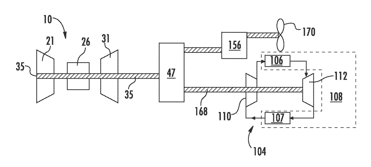
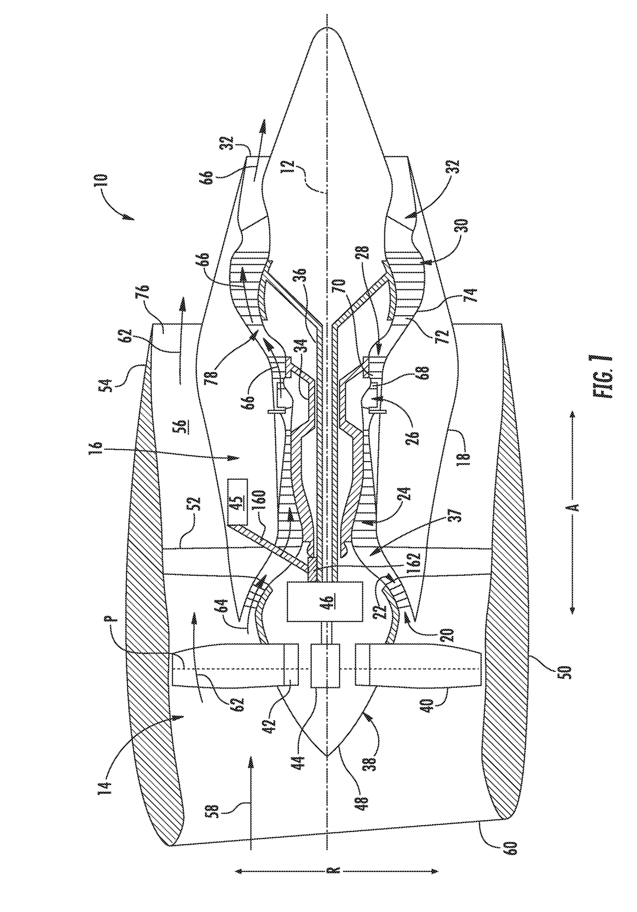
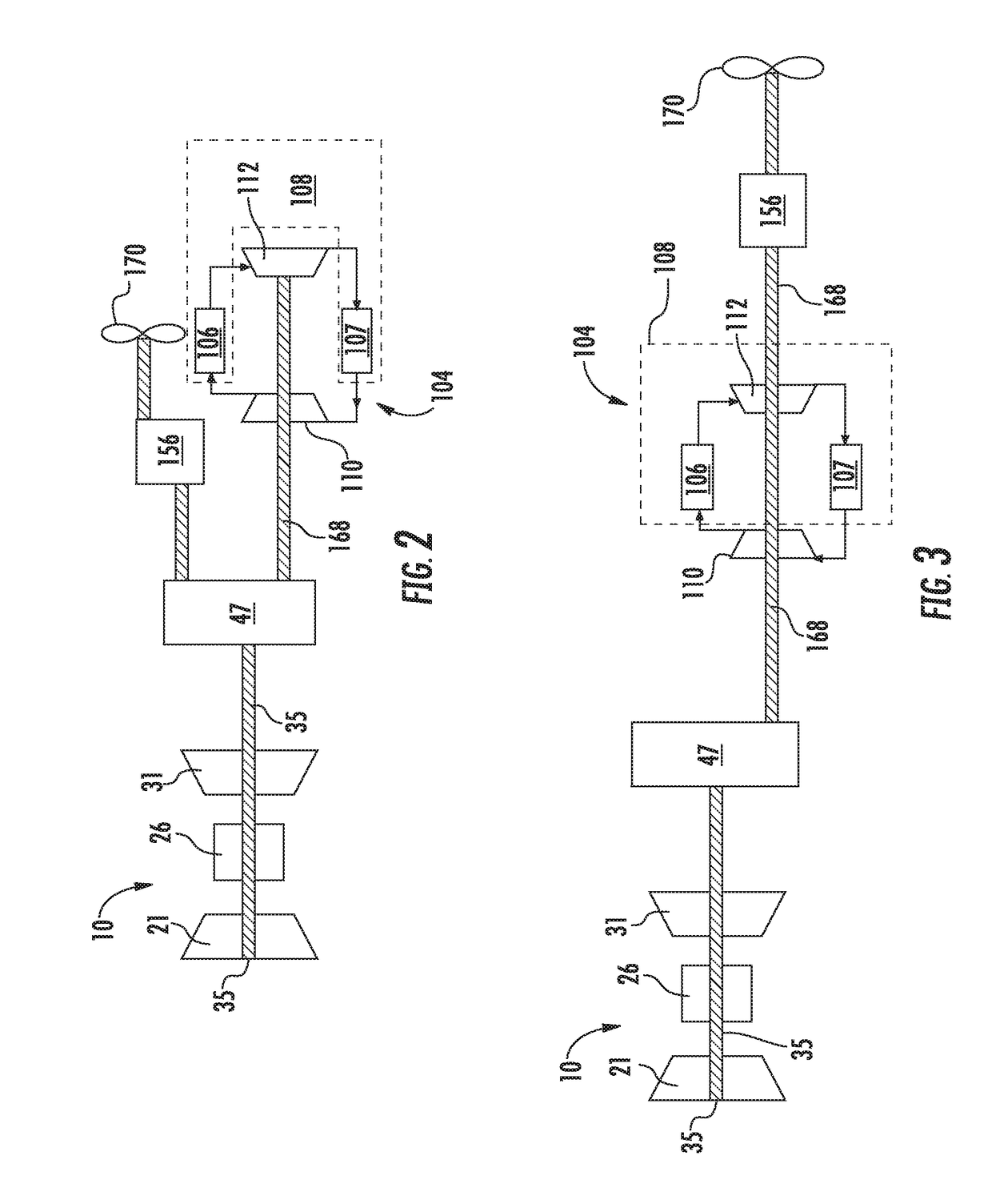
The present disclosure is directed to an aircraft power generation system including a reverse Brayton cycle system, a gas turbine engine, and a gearbox. The gas turbine engine includes a compressor section, a turbine section, and an engine shaft. The compressor section is arranged in serial flow arrangement with the turbine section. The engine shaft is rotatable with at least a portion of the compressor section and with at least a portion of the turbine section. The reverse Brayton cycle system includes a compressor, a driveshaft, a turbine, and a first exchanger. The driveshaft is rotatable with the compressor or the turbine, and the compressor, the first heat exchanger, and the turbine are in serial flow arrangement. The gearbox is configured to receive mechanical energy from the engine shaft and transmit mechanical energy to the reverse Brayton cycle system through the driveshaft.

Description

FIELD OF THE INFORMATION[0001]The present invention relates generally to utilizing a gas turbine engine to power aircraft systems. More particularly, the present subject matter relates to a thermal management system that is mechanically driven by a gas turbine engine.BACKGROUND OF THE INVENTION[0002]Aircraft gas turbine engines deliver propulsive thrust for aircraft movement as well as provide energy for aircraft systems, such as a thermal management system (TMS), which may include an environmental control system (ECS). The TMS further includes management of energy and heat transfer among aircraft propulsion and electrical power generation units, fluid heat exchangers, electronics cooling, and an environmental control system (ECS), which provides conditioned air to an aircraft cabin, storage, and avionics. The ECS generally includes a reverse Brayton cycle system (RBC) that is pneumatically driven by compressed air that is diverted from the propulsive engines, as well as ducting and...

Claims


Application Information

Patent Timeline
Patent Type & Authority Applications(United States)
IPC IPC(8): F01D15/12F04D29/32F01D5/02F01D13/00F25B9/10F01D11/24B64D13/06B64D27/10F25B9/00F25B9/14F04D29/58F01D13/02
CPCF01D11/24F01D13/02B64D27/10F25B9/004F25B9/008F25B9/14F25B9/10F05D2220/323F05D2240/24F05D2240/60F05D2260/40311F05D2260/606F05D2260/213B64D2013/0618F25B2309/004F25B2309/005F01D15/12F04D29/5826F04D29/321F01D5/02F01D13/003F01D13/006B64D13/06F02C7/32F02C7/36F02C7/12F02C7/18F02C6/08F02C6/18F02C9/18Y02T50/60
Inventor BRINSON, THOMAS EDWARDGEMIN, PAUL ROBERT
Owner GENERAL ELECTRIC CO
Learn More