Redundant Reciprocal Tracking System

Active Publication Date: 2018-02-22
ATRACSYS SARL
View PDF14 Cites 22 Cited by
  • Summary
  • Abstract
  • Description
  • Claims
  • Application Information

AI Technical Summary

Benefits of technology

[0041]In an embodiment of the tracking system, the redundancy of the

Problems solved by technology

This error give the possibility to provide a rejection threshold on the pose measurement.
The lack of redu

Method used


Image

  • Redundant Reciprocal Tracking System
  • Redundant Reciprocal Tracking System
  • Redundant Reciprocal Tracking System

Examples


Embodiment Construction

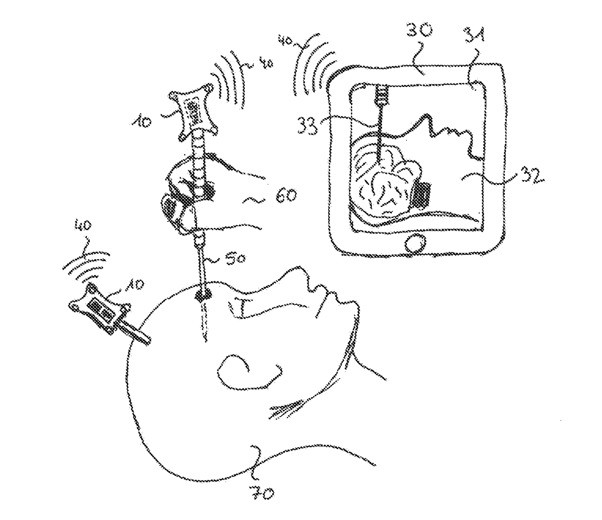
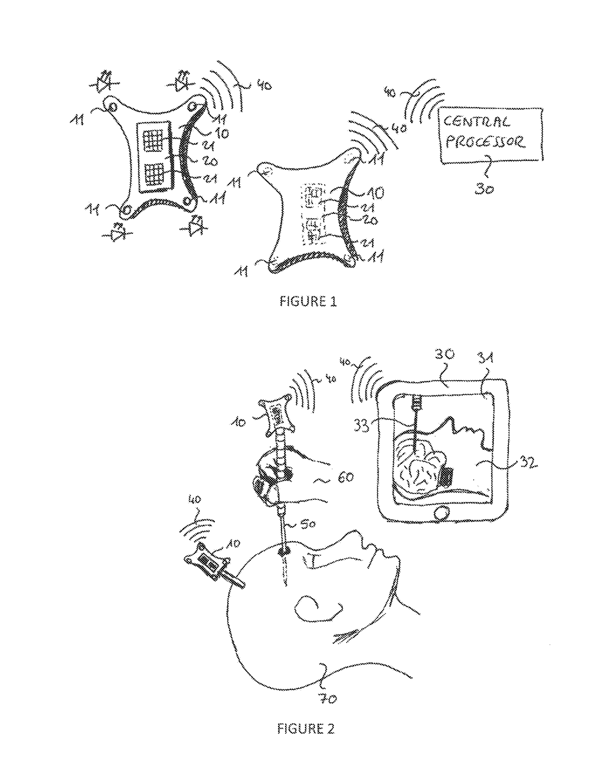
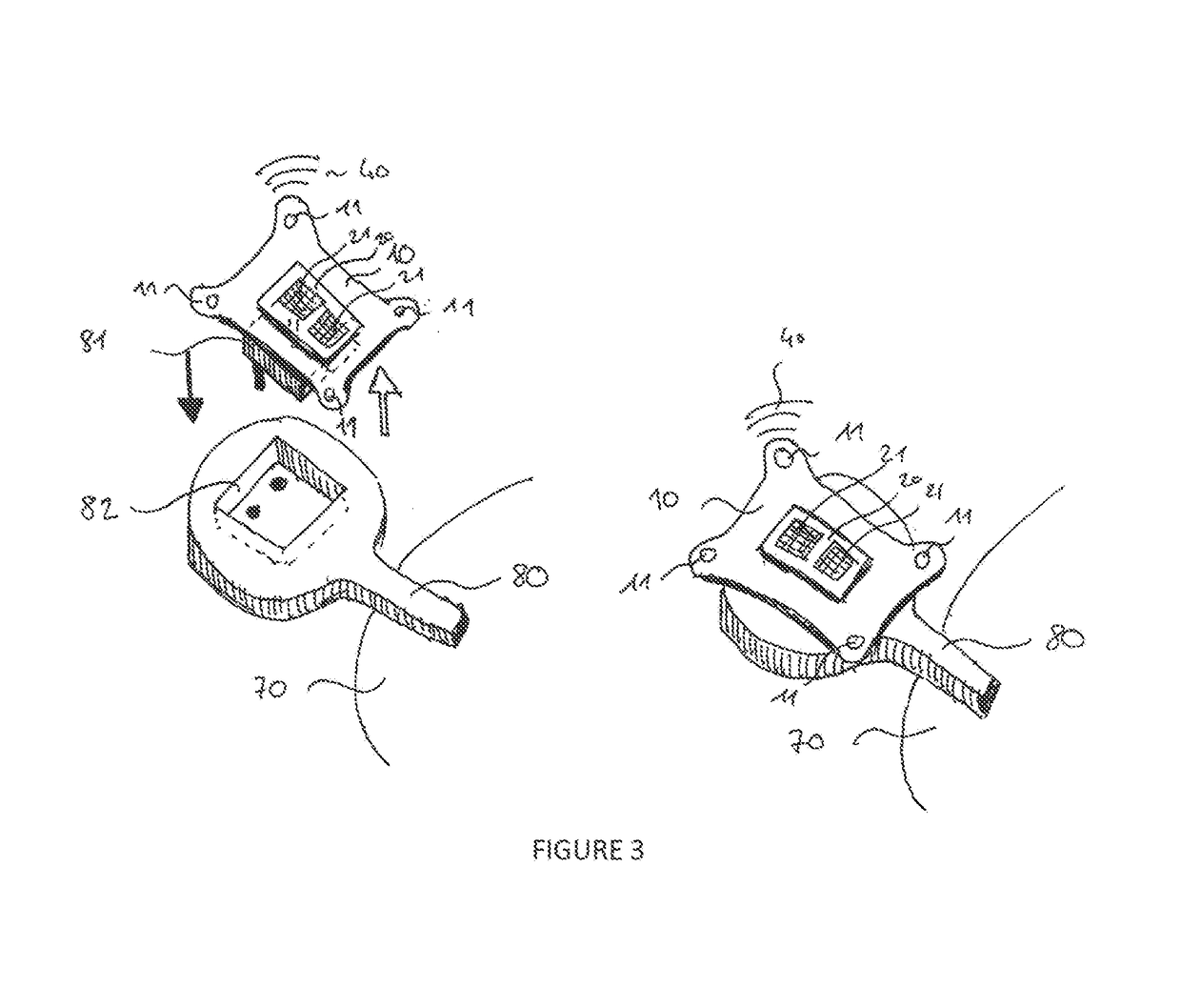
[0056]FIG. 1 presents as an embodiment of the invention an optical variation of a Redundant Reciprocal Tracking System, which is comprises two Trackers 10. They are facing each other in the figure. Four Light Sources—or Sensed Elements 11—are rigidly fixed to each Trackers. Each Trackers comprises a sensor sub-assembly 20 fixed with respect to the Light Source(s). The Sensor sub-assembly comprises two 2D Optical Sensor Modules 21. This Sensor sub-assembly is able to detect the 3D positions (with 4 DoF) of the distinct Light Sources located on the other Tracker via triangulation of the two Optical Sensors Modules. The over-determination of the 3D measure enabling to get information either on Tracker decalibration or measurement problem. If three or more Light Sources present on the other Tracker are detected, it is also possible to calculate the pose (position+orientation) of the other Tracker. The other Tracker can symmetrically or reciprocally perform the same type of measurement b...


PUM


Abstract

The present invention relates to a redundant reciprocal tracking system composed of at least two trackers 10. A first tracker is able to sense partial or full pose data (orientation and position) of a second tracker in a first reference frame and the second tracker is able to sense partial or full pose data of the first tracker in a second reference frame. Pose data of first and second trackers are further transferred to a central processor 30, which is able to compute the transformation between first and second reference frame. Data generated by the trackers are such designed that they define an over-determined mathematical system (e.g. more than 6 degrees of freedom in a 3D setup). The over-determined information can be used to qualify and/or improve the transformation of the reference frame. In an embodiment of the invention, the tracking system is an optical one and the over-determined information defines an error metric used to check the validity of the transformation. Such setup could be used in surgical navigation system in order to reduce the risk of injury or death of the patient.

Description

CORRESPONDING APPLICATION[0001]The present application claims priority to U.S. provisional application U.S. Ser. No. 62 / 128,585 filed on Mar. 5, 2015, the content of this earlier application being incorporated by reference in its entirety in the present application.FIELD OF THE INVENTION[0002]The present invention relates generally to redundant reciprocal tracking systems and more specifically it relates to an optical tracking system where at least two trackers are sensing each other in order to compute a rigid transformation based on an over-determined system.BACKGROUND OF THE INVENTION[0003]Optical tracking systems for tracking the pose (that is the position and orientation) of moving objects in a reference frame or system are known in the literature and prior art. These tracking devices usually use one or several camera sensors. For example, in U.S. Pat. No. 5,227,985 issued to Daniel F. De Menthon, and entitled “Computer vision system for position monitoring in three dimensions ...

Claims


Application Information

Patent Timeline
IPC IPC(8): A61B34/20A61B34/30A61B90/00
CPCA61B34/20A61B34/30A61B90/37A61B2034/2057A61B2090/372A61B2017/00221A61B2090/3983A61B2090/0818A61B2034/2055G01S5/16G01S5/163
Inventor MARTI, GAETANHALG, MAURICE
Owner ATRACSYS SARL
Why Eureka
Try Eureka