An improved chest drainage system and method

a drainage system and chest technology, applied in the field of chest drainage system, can solve problems such as the risk factor of chest tube infection, and achieve the effect of effectively excluding the risk of infection

Active Publication Date: 2018-02-22
REGION SYDDANMARK
View PDF4 Cites 2 Cited by
  • Summary
  • Abstract
  • Description
  • Claims
  • Application Information

AI Technical Summary

Benefits of technology

[0016]The invention is particularly, but not exclusively, advantageous for obtaining an improved chest drainage system for creating and maintaining a sub-atmospheric pressure within the pleural cavity and / or the mediastinum of an associated patient, which is significantly cheaper to implement than hitherto known spectroscopic detection methods, where electromagnetic radiation is scattered and / or absorbed by the carbon dioxide (amount of a few percentages) thereby enabling dedicated optical detectors to determine the presence, and possibly amount, of carbon dioxide in the air arriving at the chest drainage unit or chest drainage canister. It is a particular advantage of the present invention that the carbon dioxide sensor provides a visible color change, which enables direct and simple detection (i.e. color or not?) at the bed side without any complex and / or costly electronic detection of the carbon dioxide level. The carbon dioxide sensor of the present invention is also independent of any continuously supplied power or energy.
[0017]Moreover, preliminary tests performed by the inventor (and presented below) have demonstrated that the present invention is very effective in determine whether, or not, carbon dioxide is present in the air passing through the chest drainage unit, this information being highly important in the subsequent decision of continuing the treatment with the chest drainage system, terminating the treatment with the chest drainage system, and / or doing a surgical replacement of the chest tube in the patient. Thereby, risks are eliminated, averted and / or reduced to the overall benefit of the patient by improved medical treatment by a chest drainage system according to the present invention. In particular, a chest tube is a risk factor due to possible infections in the connection with the inserted chest tube.
[0018]Beneficially, the present invention also improves assessment and / or implementation of the chest drainage treatment so that there is less need for experts in determining a possible pleural leakage, in fact nurses may immediately see if there is leakage, which has hitherto been a rather difficult task, possibly even requiring a very experienced doctor. Thus, for the clinic or hospital performing thorax surgery or for general hospitals treating uncomplicated collapses of the lung etc., the present invention provides numerous advantages.
[0019]In the context of the present invention, it is to be understood that the present invention is related to a chest drainage system, or chest drainage unit, for creating and maintaining a sub-atmospheric pressure within the pleural cavity and / or the mediastinum of an associated patient, but it will also be understood that the invention may also be applied in related medical conditions with similar situations and / or causes, as it will be understood by the person skilled in thorax surgery and neighbouring technical fields, once the teaching and general principle of the present invention is fully understood.
[0020]In the context of the present invention, the patient is not part of the drainage system and, hence, in the above definition of the invention, the patient is mentioned merely for clarity and completeness of the invention without being part of the system itself, i.e. the patient is ‘associated’ with the system—not part of it.
[0021]In the context of the present invention, it is further to be understood that the internal cavity in the chest drainage unit (CDU) may have at least two chamber parts, i.e. at least the first and the second chamber part, but for some applications or situations more chamber parts are envisioned within the scope of the present invention.

Problems solved by technology

In particular, a chest tube is a risk factor due to possible infections in the connection with the inserted chest tube.

Method used


Image

  • An improved chest drainage system and method
  • An improved chest drainage system and method
  • An improved chest drainage system and method

Examples


Embodiment Construction

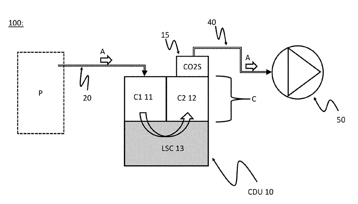
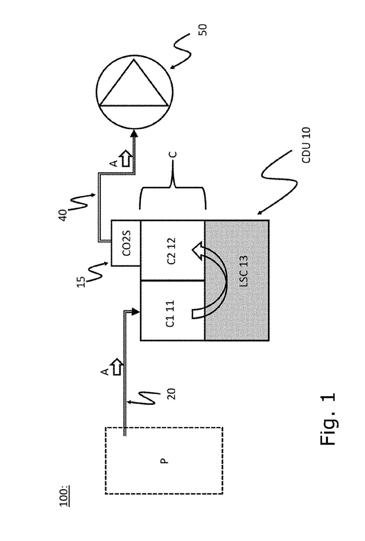
[0056]FIG. 1 schematically shows a chest drainage system 100 according to the invention.

[0057]The chest drainage system is capable and specifically arranged for creating and maintaining a sub-atmospheric pressure within the pleural cavity and / or the mediastinum of an associated patient P (as symbolically indicated with the hatched lines). The drainage system comprises a flexible chest tube 20 adapted for insertion into the chest of said associated patient P and arranged for conveying air A (schematically indicated by the arrow) from the chest, as already known in the field, more particularly when performing drainage treatment after thorax surgery, cf. Kirsch T D. Tube Thoracostomy. In: Roberts J R, Hedges J R, eds. Clinical Procedures in Emergency Medicine. 5th ed. Philadelphia, Pa.: Saunders Elsevier; 2009: chapter 10, which is hereby incorporated by reference in its entirety.

[0058]Additionally, a chest drainage unit CDU 10 is connected to the said flexible chest tube 40 for creati...


PUM


Abstract

The invention relates to a chest drainage system (100) for creating and maintaining a sub-atmospheric pressure within the pleural cavity and / or the mediastinum of a patient (P). The system has a chest drainage unit (CDU, 10) with an internal cavity (C) having a first chamber part (C1, 11) and a second chamber part (C2, 12) with an air outlet from the CDU, and a liquid seal chamber (LSC, 13). The second chamber part (C2, 12) of the chest drainage unit is connected to a carbon dioxide sensor (CO2S, 15) for detecting carbon dioxide in any air passing through the liquid seal chamber (LSC, 13), the carbon dioxide sensor being capable of detecting carbon dioxide by a visible color change from a chemical reaction occurring in the carbon dioxide sensor between carbon dioxide and a detector reactant (DC) positioned in the carbon dioxide sensor. Preliminary test performed by the inventor have demonstrated that the present invention is very effective in determine whether, or not, carbon dioxide is present in the air passing through the chest drainage unit, this information being highly important in the subsequent decision of continuing the treatment with the chest drainage system.

Description

FIELD OF THE INVENTION[0001]The present invention relates to a chest drainage system and a corresponding method for application on patients after thorax surgery where drainage of fluids and restoration of the pleural cavity and / or the mediastinum are required.BACKGROUND OF THE INVENTION[0002]Following thorax surgery of a patient, it is often necessary to perform postoperative drainage of the mediastinal space, the pericardial space and particularly the pleural space. Drainage holes are placed in the patient and a dedicated chest tube is positioned through the incision, often secured by suture. The chest tube is then connected to a drainage canister, or drainage unit, and further connected to an optionally suction pump capable of removing fluids and create the required moderate sub-atmospheric pressure in the pleural space of the patient.[0003]Air leakage from the lung after such pulmonary surgery is present in nearly all patients and routinely treated with a chest tube connected to ...

Claims


Application Information

Patent Timeline
Patent Type & Authority Applications(United States)
IPC IPC(8): A61M1/00
CPCA61M1/0025A61M2205/3324A61M1/0013G01N33/004A61M2210/101A61M2202/0225A61M2205/0227A61M1/61A61M1/73A61M1/64A61M1/60
Inventor ECKARDT, JENS
Owner REGION SYDDANMARK
Why Eureka
Try Eureka