
Fingerprint module, method for fabricating the same, and mobile terminal having the same

a fingerprint module and mobile terminal technology, applied in the field of fingerprint modules, can solve the problems of poor production quality and defective fingerprint modules

Active Publication Date: 2018-02-22
GUANGDONG OPPO MOBILE TELECOMM CORP LTD
View PDF13 Cites 7 Cited by
  • Summary
  • Abstract
  • Description
  • Claims
  • Application Information

AI Technical Summary

Benefits of technology

The present patent provides a fingerprint module, a method for making it, and a mobile terminal. By coating adhesive on the inner surface of the cover plate and laminating the fingerprint chip onto it, the adhesive fully contacts the cover plate and fingerprint chip, making the fingerprint chip tightly combined with the cover plate and difficult to detach. This improves the quality of the fingerprint module.

Problems solved by technology

However, due to relatively light weight nature of the fingerprint chip, the fingerprint chip becomes easily detached from the cover plate by other components when being fixed to the cover plate, which leads to defectiveness of the fingerprint module and causes poor production quality.

Method used


Image

  • Fingerprint module, method for fabricating the same, and mobile terminal having the same
  • Fingerprint module, method for fabricating the same, and mobile terminal having the same
  • Fingerprint module, method for fabricating the same, and mobile terminal having the same

Examples


first embodiment

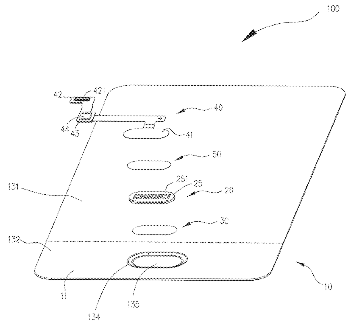
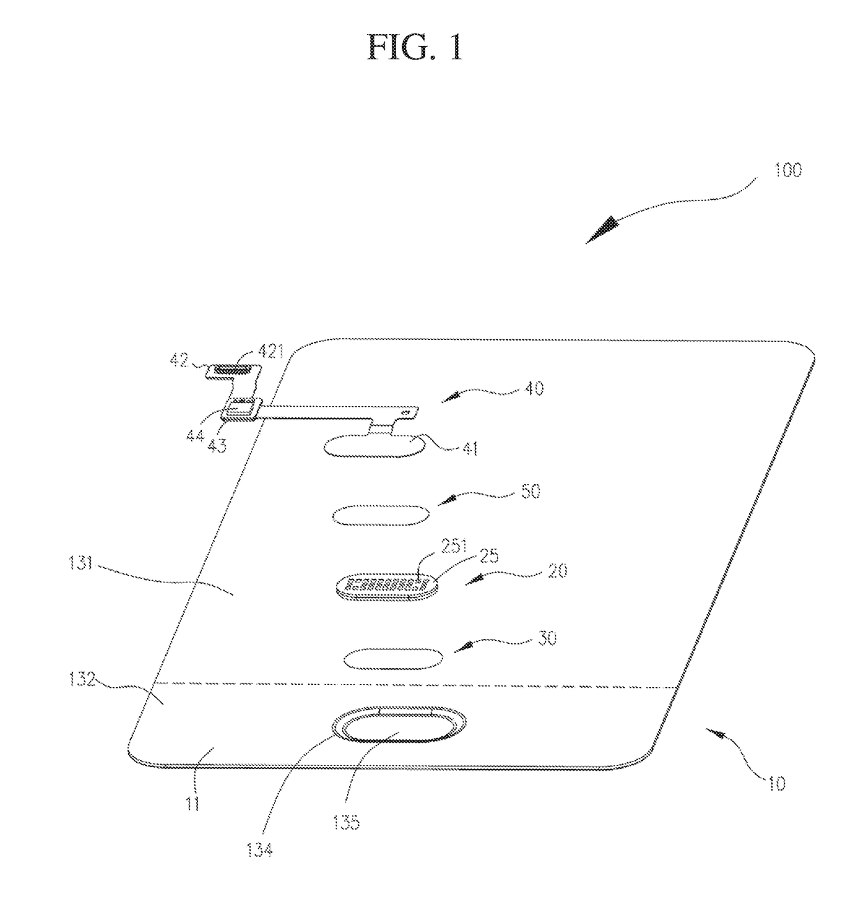
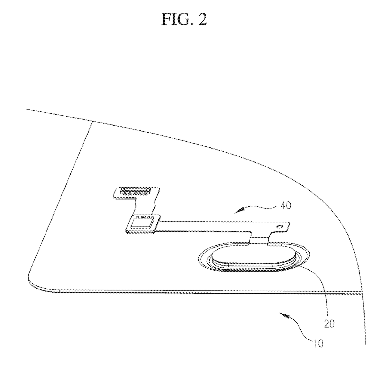
[0019]The cover plate 10 can be a mobile phone front cover or a mobile phone back cover. A first embodiment is provided, and the mobile phone front cover is used as an example for illustration. Specifically, the cover plate 10 is used to cover with a display screen 203 of the mobile terminal 200. The cover plate 10 includes an outer surface 12 and an inner surface 11 disposed with respect to the outer surface 12. The outer surface 12 faces a user, and the inner surface 11 is used to fit the motherboard 203. The inner surface 11 includes a light-transmitting region 131 and a shading region 132 adjacent to a bottom end of the light-transmitting region 131. Light emitted by the display screen 203 (shown in FIG. 8) passes through the light-transmitting region 131. An ink layer 133 is coated on the shading region 132 and is used to shield light emitted by display screen 203 from passing through a non-display region, thereby preventing the display screen 203 from leaking. The fingerprint ...

third embodiment

[0027]Please refer to FIG. 5. The present disclosure provides a third embodiment, which the fingerprint chip 20 is electrically coupled to the circuit board 40 by a board-to-board connector 60. Specifically, the board-to-board connector 60 includes a socket 61 and a plug 62. The socket 61 is soldered onto the connecting surface 25 of the fingerprint chip 20. The socket 61 is electrically coupled to the solder pad 251. The plug 62 is soldered onto the circuit board 40 and located at the first end 41. The circuit board 40 is located at the first end, and a reinforcement 45 is disposed on a side of the circuit board 40 opposite to the plug 42 so as to enhance a bonding strength of the plug 62 with the socket 61. By disposing the board-to-board connector 60 between the adapter plate 23 and the circuit board 40, weight of the fingerprint chip 20 is increased to enhance a pressing force of the fingerprint chip 20 to the adhesive 30, so that the fingerprint chip 20 is more secured with the...


PUM


Abstract

A fingerprint module, a method for fabricating the same, and a mobile terminal having the same are provided. The fingerprint module has a cover plate and a fingerprint chip. The cover plate has an inner surface. The fingerprint chip is heat-pressed on the inner surface by adhesive, such that the adhesive fully contacts the cover plate and the fingerprint chip. The method includes after heating the adhesive which is coated on the inner surface of the cover plate, the fingerprint chip is laminated on the adhesive, such that the adhesive fully contacts the cover plate and the fingerprint chip.

Description

CROSS REFERENCE TO RELATED APPLICATION[0001]This application is a non-provisional patent application, which claims priority to Chinese Application No. 201610679971.2, filed on Aug. 16, 2016. The entire disclosure of the above application is incorporated herein by reference.FIELD OF THE DISCLOSURE[0002]The present disclosure relates to electronic equipment, and more particularly to a fingerprint module, a method for fabricating the same, and a mobile terminal having the fingerprint module.BACKGROUND OF THE DISCLOSURE[0003]With fingerprint identification being more and more widely used in mobile phones, there are more and more stringent demands on quality of fingerprint modules. Typically, each of the fingerprint modules includes a fingerprint chip fixed onto a cover plate. However, due to relatively light weight nature of the fingerprint chip, the fingerprint chip becomes easily detached from the cover plate by other components when being fixed to the cover plate, which leads to defe...

Claims


Application Information

Patent Timeline
IPC IPC(8): G06K9/00
CPCG06K9/0002G06K9/00053G06K9/00087G06K9/00067G06V40/12H04M1/026H04M2250/12G06F1/1696G06V40/1306G06V40/1347G06V40/1365G06V40/1329
Inventor ZHANG, WENZHEN
Owner GUANGDONG OPPO MOBILE TELECOMM CORP LTD
Learn More