Active equalizing negative resistance amplifier for bi-directional bandwidth extension

a negative resistance amplifier and bi-directional bandwidth technology, which is applied in the direction of amplifiers with semiconductor devices/discharge tubes, dc-amplifiers with dc-coupled stages, and different amplifiers. it can solve the problems of high-frequency losses in transmission lines, loss increase, and loss also increas

Active Publication Date: 2018-02-22
ADVANCED MICRO DEVICES INC
View PDF77 Cites 1 Cited by
  • Summary
  • Abstract
  • Description
  • Claims
  • Application Information

AI Technical Summary

Problems solved by technology

When high-speed data signals are transferred over signal paths, the transmitted signals can be distorted by high-frequency losses in the transmission lines.
As data signals frequencies increase, losses increase.
Similarly, as the lengths of the signal paths increase, the losses also increase.
Because the transmitted signals become distorted, errors may be introduced during transmission from the source to a receiver.

Method used


Image

  • Active equalizing negative resistance amplifier for bi-directional bandwidth extension
  • Active equalizing negative resistance amplifier for bi-directional bandwidth extension
  • Active equalizing negative resistance amplifier for bi-directional bandwidth extension

Examples


Embodiment Construction

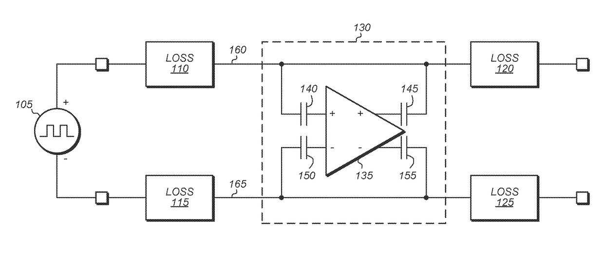
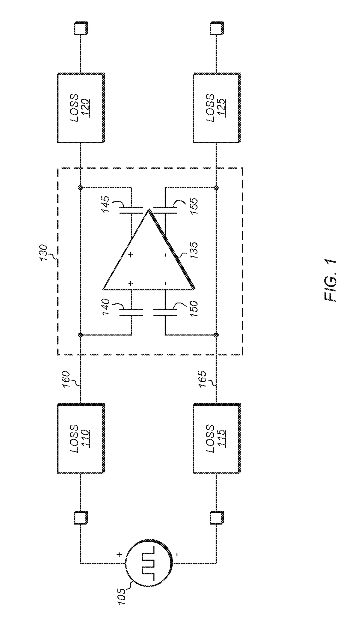
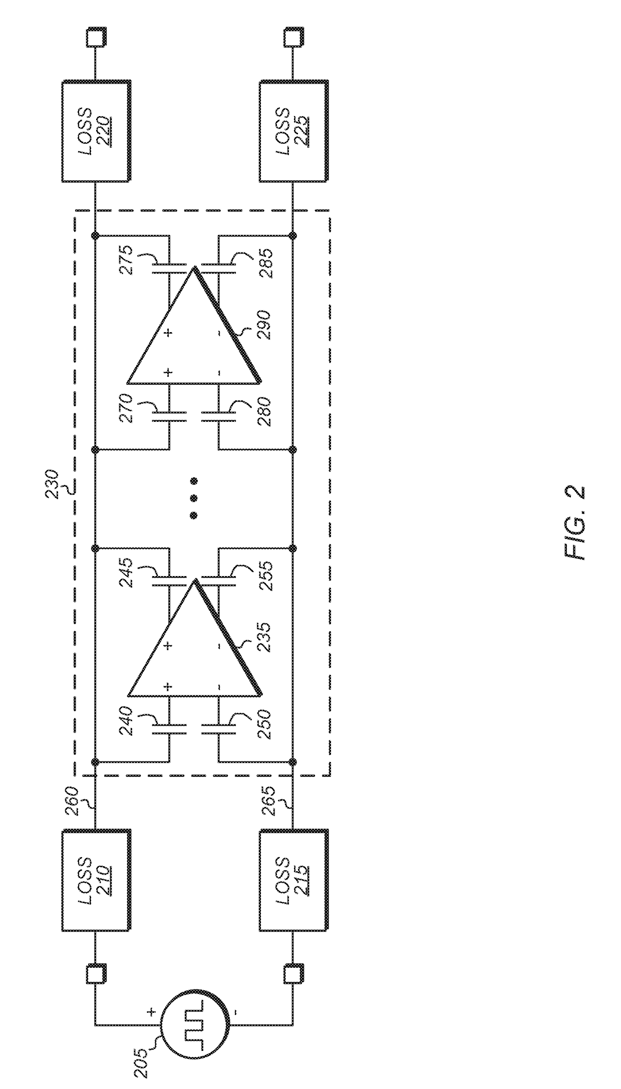
[0011]Systems, apparatuses, and methods for implementing circuits for achieving bandwidth extension are contemplated. In one embodiment, alternating current (AC) capacitors are placed on the inputs and outputs of a fully differential amplifier connecting to a high speed differential signal path. Generally speaking, a differential amplifier amplifies the difference between the voltages on two inputs and suppresses voltage that is common on the inputs. In one embodiment, a circuit includes first and second signal paths, a fully differential amplifier, and four capacitors. A first capacitor is coupled between the first signal path and a non-inverting input terminal of the amplifier and a second capacitor is coupled between the first signal path and a non-inverting output terminal of the amplifier. A third capacitor is coupled between the second signal path and an inverting input terminal of the amplifier and a fourth capacitor is coupled between the second signal path and an inverting ...


PUM


Abstract

Systems, apparatuses, and methods for implementing a negative resistance circuit for bandwidth extension are disclosed. Within a feedback path of a differential signal path, capacitors are placed on the inputs and outputs of a fully differential amplifier connecting to the differential signal path. In one embodiment, a circuit includes a fully differential amplifier and four capacitors. A first capacitor is coupled between a first signal path and a non-inverting input terminal of the amplifier and a second capacitor is coupled between the first signal path and a non-inverting output terminal of the amplifier. A third capacitor is coupled between a second signal path and an inverting input terminal of the amplifier and a fourth capacitor is coupled between the second signal path and an inverting output terminal of the amplifier. The first and second signal paths carry a differential signal.

Description

BACKGROUNDDescription of the Related Art[0001]When high-speed data signals are transferred over signal paths, the transmitted signals can be distorted by high-frequency losses in the transmission lines. As data signals frequencies increase, losses increase. Similarly, as the lengths of the signal paths increase, the losses also increase. Because the transmitted signals become distorted, errors may be introduced during transmission from the source to a receiver. Therefore, systems and methods are desired for extending the usable bandwidth of signals.BRIEF DESCRIPTION OF THE DRAWINGS[0002]The above and further advantages of the methods and mechanisms may be better understood by referring to the following description in conjunction with the accompanying drawings, in which:[0003]FIG. 1 is a block diagram of one embodiment of a fully differential amplifier capacitively coupled to a differential signal path.[0004]FIG. 2 is a block diagram of one embodiment of fully differential amplifiers...

Claims


Application Information

Patent Timeline
Patent Type & Authority Applications(United States)
IPC IPC(8): H04B1/04H03F3/45
CPCH04B1/0475H03F2203/45034H03F3/45475H03F2200/369H03F2203/45134H03F2203/45138H03H11/52
Inventor PARASCHOU, MILAMTALBOT, GERALD R.GONZALES, DEAN E.
Owner ADVANCED MICRO DEVICES INC
Why Eureka
Try Eureka