Industrial truck and method for controlling an industrial truck

a technology for industrial trucks and trucks, applied in the field of industrial trucks, can solve problems such as unfavorable optical system operation, and achieve the effect of simplifying loading and unloading for users and lifting and lowering the load portion

Active Publication Date: 2018-03-01
JUNGHEINRICH AG
View PDF13 Cites 1 Cited by
  • Summary
  • Abstract
  • Description
  • Claims
  • Application Information

AI Technical Summary

Benefits of technology

[0006]The object of the invention is to provide an industrial truck and a method for controlling an industrial truck, which make it possible to work safely with the driving industrial truck without the risk of injuries.
[0019]In another embodiment of the method, the industrial truck is stopped and / or braked if the relative position of the portable transmitting and receiving unit is located in a first spatial region which comprises a load portion of the industrial truck. If the portable transmitting and receiving unit is located in a spatial region around the load portion, this prevents the industrial truck from driving or steering, wherein any steering or driving movement is stopped and / or braked. In an embodiment, the industrial truck is stopped and / or braked in a relative position to the portable transmitting and receiving unit, which can be selected. The relative position, which can be selected, makes it possible to select one of multiple positions relative to the portable transmitting and receiving unit. For example, this can be a start or an end of the load portion.
[0023]In a further embodiment of the method, a height above the ground is determined for the mobile transmitting and receiving unit and the industrial truck is controlled depending on the height. The height-dependent control can also be used for safety reasons, for example if the height of the portable transmitting and receiving unit is located below a predetermined minimum height. In this case, the transmitting and receiving unit could have been dropped and be lying on the ground, or the person carrying said transmitting and receiving unit has fallen. Furthermore, it is possible to lift and lower the load portion depending on a height of the portable transmitting and receiving unit, considerably simplifying loading and unloading for a user.

Problems solved by technology

The disadvantage of the known method for controlling a picking vehicle is that movements of the operator in the detection range of the optical sensor can lead to unclear situations with the optical system.

Method used


Image

  • Industrial truck and method for controlling an industrial truck
  • Industrial truck and method for controlling an industrial truck
  • Industrial truck and method for controlling an industrial truck

Examples


Embodiment Construction

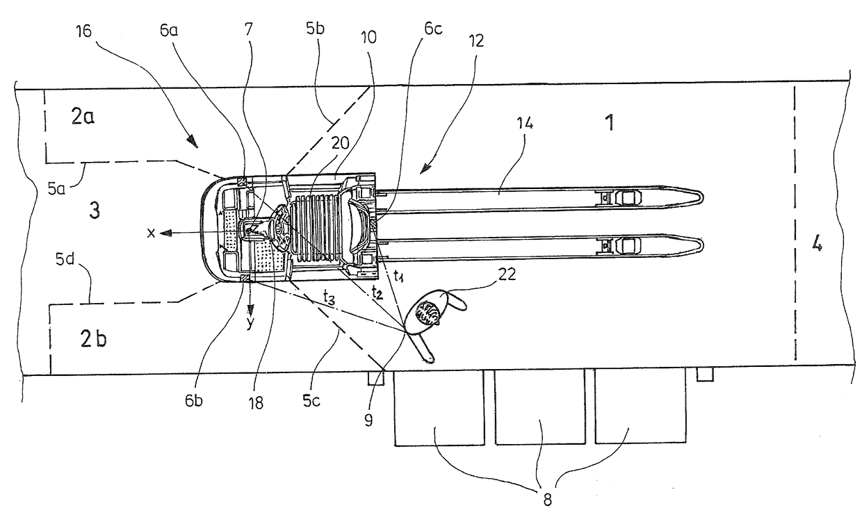
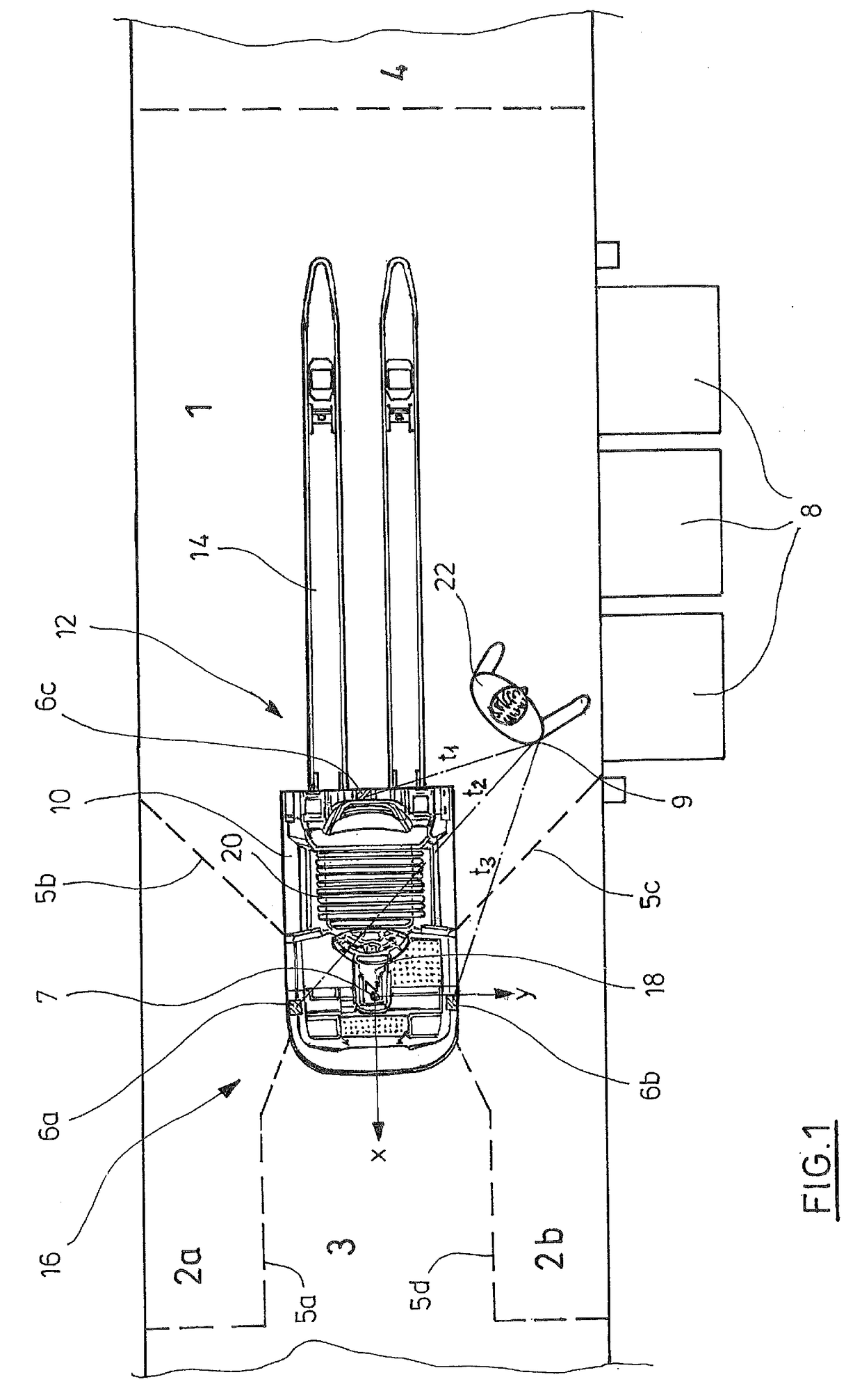
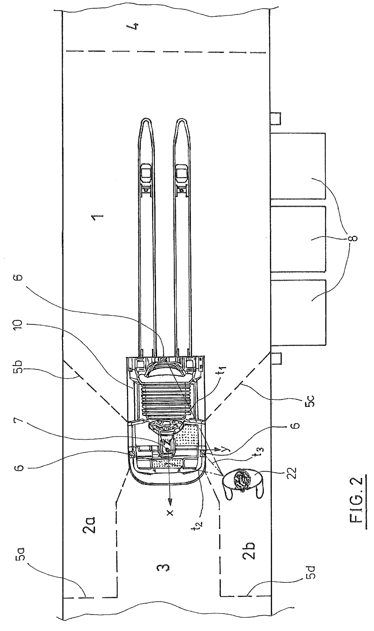
[0027]FIG. 1 shows an industrial truck or vehicle 10 in a view from above. The industrial truck 10 has a load portion 12 with two load forks 14. The load forks 14 are of sufficient length to receive multiple pallets which are configured for picking goods. A drive portion 16 of the industrial truck is configured with a short drawbar 18 and a driver position or standing platform 20. Standing at the driver position 20, a vehicle operator or driver 22 can operate the vehicle by means of the short drawbar 18.

[0028]The drive portion 16 is equipped with three transmitting and receiving units 6a, 6b, 6c. Based on the integrated coordinate system 7, the transmitting and receiving units 6a, 6b are located at the same X and Z position, at a positive and negative Y value, while the transmitting and receiving unit 6c is located at a Y value of zero. As a matter of principle, the three transmitting and receiving units 6a, 6b, 6c can generally be positioned anywhere on the industrial truck. In ord...


PUM


Abstract

A system for controlling an industrial truck with a drive portion including a traction drive portion, a steering portion, and a load portion, comprises a portable transmitting unit configured to be positioned away from the industrial truck. The system further comprises at least three transmitting and receiving units positioned in a predetermined spatial arrangement with respect to one another on the drive portion. An evaluation unit is provided that is configured to determine a position of the portable transmitting and receiving unit relative to the industrial truck by measuring signal propagation times. The industrial truck further comprises a control unit configured to send a control command for traction drive and / or steering if the relative position of the portable transmitting and receiving unit is located within a predetermined spatial region relative to the industrial truck.

Description

CROSS REFERENCE TO RELATED INVENTION[0001]This application is based upon and claims priority to, under relevant sections of 35 U.S.C. §119, German Patent Application No. 102016115703.1, filed Aug. 24, 2016, the entire contents of which are hereby incorporated by reference.BACKGROUND[0002]The present invention relates to an industrial truck, in particular a picking vehicle, and a method for controlling an industrial truck.[0003]A method for controlling an industrial truck, in which the industrial truck has an optical sensor that has a monitoring range and is connected to a control device which determines and tracks the position of a person within a predefined monitoring range was disclosed by EP 2851331 B1. Within the monitoring range, monitoring limits are defined in the form of boundary lines that the control device monitors if the position of the person has exceeded the monitoring limit. If it is established that the boundary line has been exceeded, a traction drive of the industr...

Claims


Application Information

Patent Timeline
Patent Type & Authority Applications(United States)
IPC IPC(8): B66F17/00B66F9/06B66F9/24B66F9/075
CPCB66F17/003B66F9/063B66F9/24B66F9/07509B66F9/07568B66F9/07572B66F9/0755B66F9/07581B66F9/20G05D1/0055G05D1/0214G05D1/0223G05D1/0225G01S13/74G01S13/931G05D2201/0216G05D1/028
Inventor GOEPNER, OLIVERSCHULER, MICHAEL
Owner JUNGHEINRICH AG
Why Eureka
Try Eureka