Self-Leveling Scope Mount and Method

a self-leveling and scope technology, applied in the field of telescopic scope mounts, can solve the problems of miscalculation target missed, and achieve the effect of improving the accuracy of the expected amount of bullet drop

Active Publication Date: 2018-03-01
LIGHTFORCE USA
View PDF1 Cites 13 Cited by
  • Summary
  • Abstract
  • Description
  • Claims
  • Application Information

AI Technical Summary

Benefits of technology

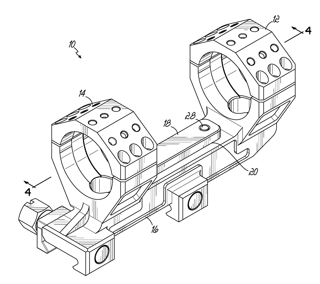
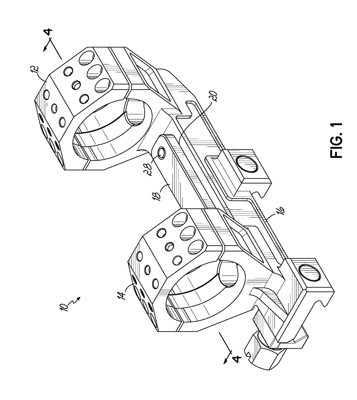
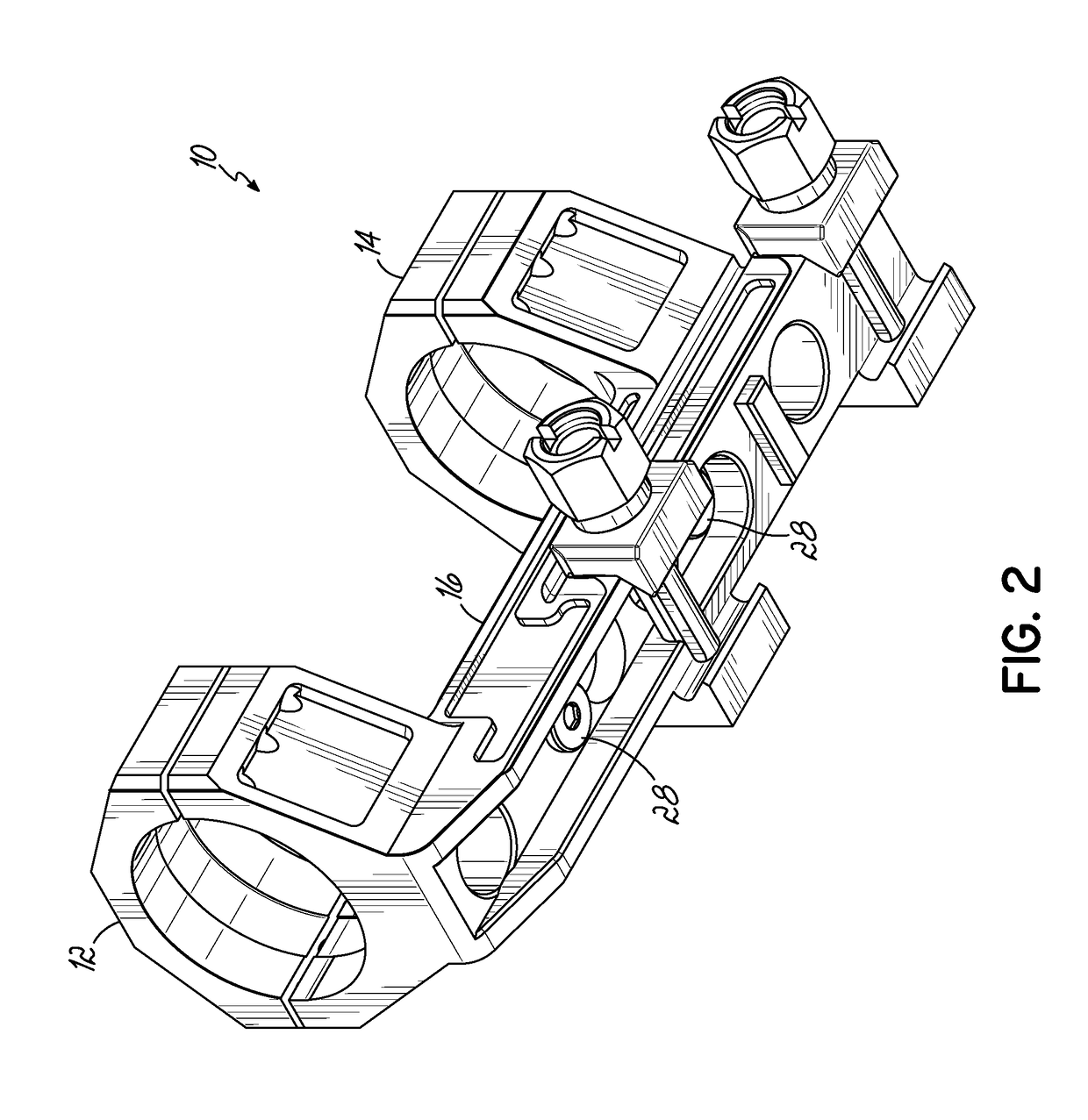
[0007]According to one embodiment, a self-leveling mount is provided for attaching a sighting scope, having a longitudinal optical axis, to a firearm, having a longitudinal barrel axis. The mount may include a body attachable to a firearm, a pair of scope attachment rings axially spaced apart relative to the body so that at least a portion of the body is situated between the attachment rings, and a vertically movable contact plate on the base between the rings. The plate presents an upper surface that is horizontally perpendicular to the longitudinal axes of a firearm barrel and scope held by the attachment rings. The contact plate may be vertically adjustable to provide alignment contact with a bottom surface of the scope held by the attachment rings to properly orient the scope relative to the firearm.

Problems solved by technology

Because riflescopes are typically used for aiming at targets a sufficient distance away from the shooter that the projectile will drop by force of gravity an appreciable distance before reaching the target, if the reticle of the scope is not properly oriented relative to the barrel, the “drop” will appear to have a lateral component, causing the target to be missed or the expected amount of bullet drop to be miscalculated.

Method used


Image

  • Self-Leveling Scope Mount and Method
  • Self-Leveling Scope Mount and Method
  • Self-Leveling Scope Mount and Method

Examples


Embodiment Construction

[0017]With reference to the drawing figures, this section describes particular embodiments and their detailed construction and operation. Throughout the specification, reference to “one embodiment,”“an embodiment,” or “some embodiments” means that a particular described feature, structure, or characteristic may be included in at least one embodiment. Thus appearances of the phrases “in one embodiment,”“in an embodiment,” or “in some embodiments” in various places throughout this specification are not necessarily all referring to the same embodiment. Furthermore, the described features, structures, and characteristics may be combined in any suitable manner in one or more embodiments. In view of the disclosure herein, those skilled in the art will recognize that the various embodiments can be practiced without one or more of the specific details or with other methods, components, materials, or the like. In some instances, well-known structures, materials, or operations are not shown o...


PUM


Abstract

Provided is a self-leveling mount for attaching a sighting scope, having a longitudinal optical axis, to a firearm, having a longitudinal barrel axis. The mount includes a body attachable to a firearm, a pair of scope attachment rings axially spaced apart relative to the body so that at least a portion of the body is situated between the attachment rings, and a vertically movable contact plate on the base between the rings. The plate presents an upper surface that is horizontally perpendicular to the longitudinal axes of a firearm barrel and scope held by the attachment rings. The contact plate makes adjustable alignment contact with a bottom surface of the scope held by the attachment rings to properly orient the scope relative to the firearm.

Description

RELATED APPLICATIONS[0001]This application claims priority to U.S. Provisional Patent Application No. 62 / 378,877, filed Aug. 24, 2016, and incorporates the same herein by reference.FIELD OF THE INVENTION[0002]The present invention relates to an apparatus for mounting a telescopic sight (rifle scope) to a firearm, air gun, or crossbow. More particularly, it relates to a mount that assures correct positioning of the scope and its internal sighting reticle relative to the firearm.BACKGROUND OF THE INVENTION[0003]Telescopic sights or riflescopes are used for precisely aiming firearms. To provide an accurate aiming indication, particularly for longer-range shots, it is important that the scope and its internal sighting reticle are properly positioned over the barrel of the firearm. The reticle, which typically includes at least one horizontal line and one vertical line, must be oriented relative to the barrel such that the horizontal crosshair is exactly level when the vertical crosshair...

Claims


Application Information

Patent Timeline
Patent Type & Authority Applications(United States)
IPC IPC(8): F41G1/44F41G1/54F41G1/387F41G1/46
CPCF41G1/44F41G1/545F41G1/387F41G1/46F41G11/003
Inventor MINOR, GRANT MATTHEW WELDRUNIA, COREY Q.
Owner LIGHTFORCE USA
Why Eureka
Try Eureka