
Driving circuit and liquid crystal display apparatus

Active Publication Date: 2018-03-01
TCL CHINA STAR OPTOELECTRONICS TECH CO LTD
View PDF2 Cites 3 Cited by
  • Summary
  • Abstract
  • Description
  • Claims
  • Application Information

AI Technical Summary

Benefits of technology

The patent aims to address the issues of solder skip and damage to display panels and driver chips in liquid crystal display apparatuses. The present invention provides a driver circuit and a liquid crystal display apparatus that can detect and prevent abnormal display or panel burnout. This is achieved by generating a detection signal and controlling power output based on the detection results.

Problems solved by technology

Currently, with the development of large-size and high-resolution liquid crystal display (LCD) televisions, the size of the connector connecting the driving board with the liquid crystal display panel is becoming larger and larger and the number of terminals is increasing more and more, easily causing the solder skip problem on the terminals located in the middle region of the connector; that is, the terminals of the connector cannot effectively connect the printed circuit board (PCB), and moreover the flexible flat cable (FFC) used together with the connector is becoming wider, making assembly difficult, and causing the FFC to be misalignedly connected, thereby leading to an abnormal display of the display panel, and possibly leading to the burnout of the liquid crystal display panel and the driver chip.

Method used


Image

  • Driving circuit and liquid crystal display apparatus
  • Driving circuit and liquid crystal display apparatus
  • Driving circuit and liquid crystal display apparatus

Examples


Embodiment Construction

[0040]The following description of the embodiments with reference to the accompanying drawings is used to illustrate particular embodiments of the present invention. The directional terms referred in the present invention, such as “upper”, “lower”, “front”, “back”, “left”, “right”, “inner”, “outer”, “side surface”, etc. are only directions with regard to the accompanying drawings. Therefore, the directional terms used for describing and illustrating the present invention are not intended to limit the present invention. In the drawings, units with similar structures are indicated by the same reference number.

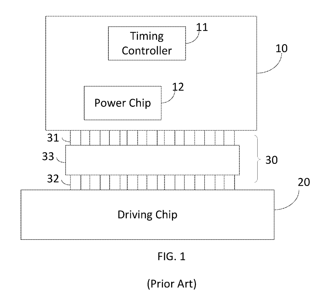
[0041]Please refer to FIG. 1, which is a structural schematic diagram of a driving circuit in a prior art.

[0042]As shown in FIG. 1, a conventional liquid crystal panel driving circuit includes a printed circuit board 10, a driver chip 20, and a flexible connector 30. The printed circuit board 10 includes a timing controller 11 (TCON) and a power chip 12. The timing controller 11 ...


PUM


Abstract

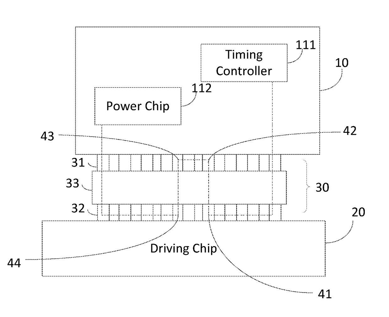
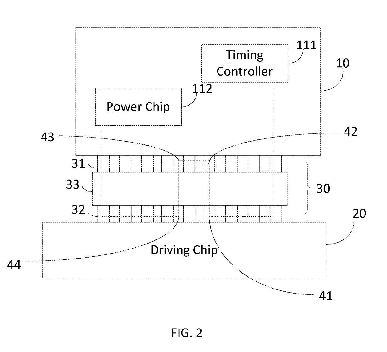
A driving circuit and a liquid crystal display apparatus are provided. The driving circuit includes a printed circuit board, which includes a timing controller for providing a detection signal to a flexible connector, wherein the detection signal is used for testing connection reliability of the flexible connector, and a power chip tier detecting whether the detection signal returned from the flexible connector is received to obtain a detection result, and controlling power output based upon the detection result.

Description

FIELD OF THE INVENTION[0001]The present invention relates to the field of display technology, and particularly to a liquid crystal display apparatus and a driving circuit.BACKGROUND OF THE INVENTION[0002]Currently, with the development of large-size and high-resolution liquid crystal display (LCD) televisions, the size of the connector connecting the driving board with the liquid crystal display panel is becoming larger and larger and the number of terminals is increasing more and more, easily causing the solder skip problem on the terminals located in the middle region of the connector; that is, the terminals of the connector cannot effectively connect the printed circuit board (PCB), and moreover the flexible flat cable (FFC) used together with the connector is becoming wider, making assembly difficult, and causing the FFC to be misalignedly connected, thereby leading to an abnormal display of the display panel, and possibly leading to the burnout of the liquid crystal display pan...

Claims


Application Information

Patent Timeline
IPC IPC(8): G09G3/20G09G3/36
CPCG09G3/2092G09G3/3611G09G2300/0408G09G2310/0264G09G2310/08G09G2330/12G09G3/3648G09G3/3696G09G3/006G09G2300/0426G09G2330/045G09G3/36
Inventor WANG, MINGLIANG
Owner TCL CHINA STAR OPTOELECTRONICS TECH CO LTD
Learn More