High frequency module

a high-frequency module and module technology, applied in the field of high-frequency modules, can solve the problems of difficult to provide, improve improve the isolation characteristics, etc., and achieve the harmonic attenuation characteristics of the transmission filter excellent, and the isolation characteristics excellent

Active Publication Date: 2018-03-01
MURATA MFG CO LTD
View PDF2 Cites 40 Cited by
  • Summary
  • Abstract
  • Description
  • Claims
  • Application Information

AI Technical Summary

Benefits of technology

[0008]Preferred embodiments of the present invention provide high frequency modules that are excellent in isolation characteristics and also excellent in harmonic attenuation characteristics of a transmission filter.

Problems solved by technology

However, the high frequency module disclosed in International Publication No. 2015 / 019722 does not take it into consideration to provide both the improvement in isolation characteristics and the improvement in harmonic attenuation characteristics of the transmission filter at the same time.
As such, with the high frequency module disclosed in International Publication No. 2015 / 019722, it is difficult to provide, at the same time, the improvement in isolation characteristics and the improvement in harmonic attenuation characteristics of the transmission filter.

Method used


Image

  • High frequency module
  • High frequency module
  • High frequency module

Examples


first circuit example

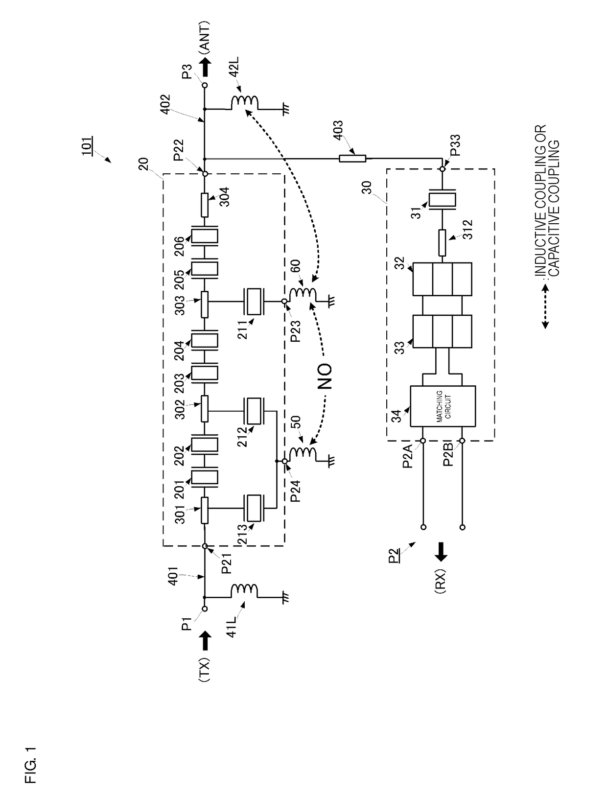
[0071]In the duplexer 101 as shown in FIG. 1, the inductor 50 and the inductor 60 obstruct electromagnetic field coupling between the inductors 50 and 60. For example, a ground is located between the inductor 60 and the inductor 50, or the inductor 60 and the inductor 50 are spaced with a distance therebetween longer than a distance between the inductor 60 and the inductor 42L. This significantly reduces or prevents the generation of electromagnetic field coupling between the inductor 50 and the inductor 60, and thus the inductor 60 and the inductor 50 are able to be separately adjusted.

[0072]The inductor 60, which is not coupled to the inductor 50 by electromagnetic field coupling, and the inductor 42L include electromagnetic field coupling (capacitive coupling or inductive coupling) generated therebetween. With this electromagnetic field coupling, an adjustment path that adjusts the isolation characteristics is defined. The adjustment path includes the connection conductor 303, th...

second circuit example

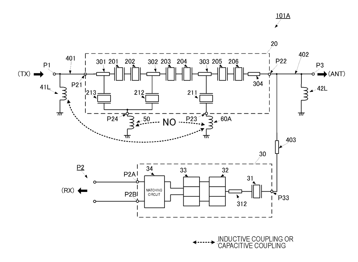
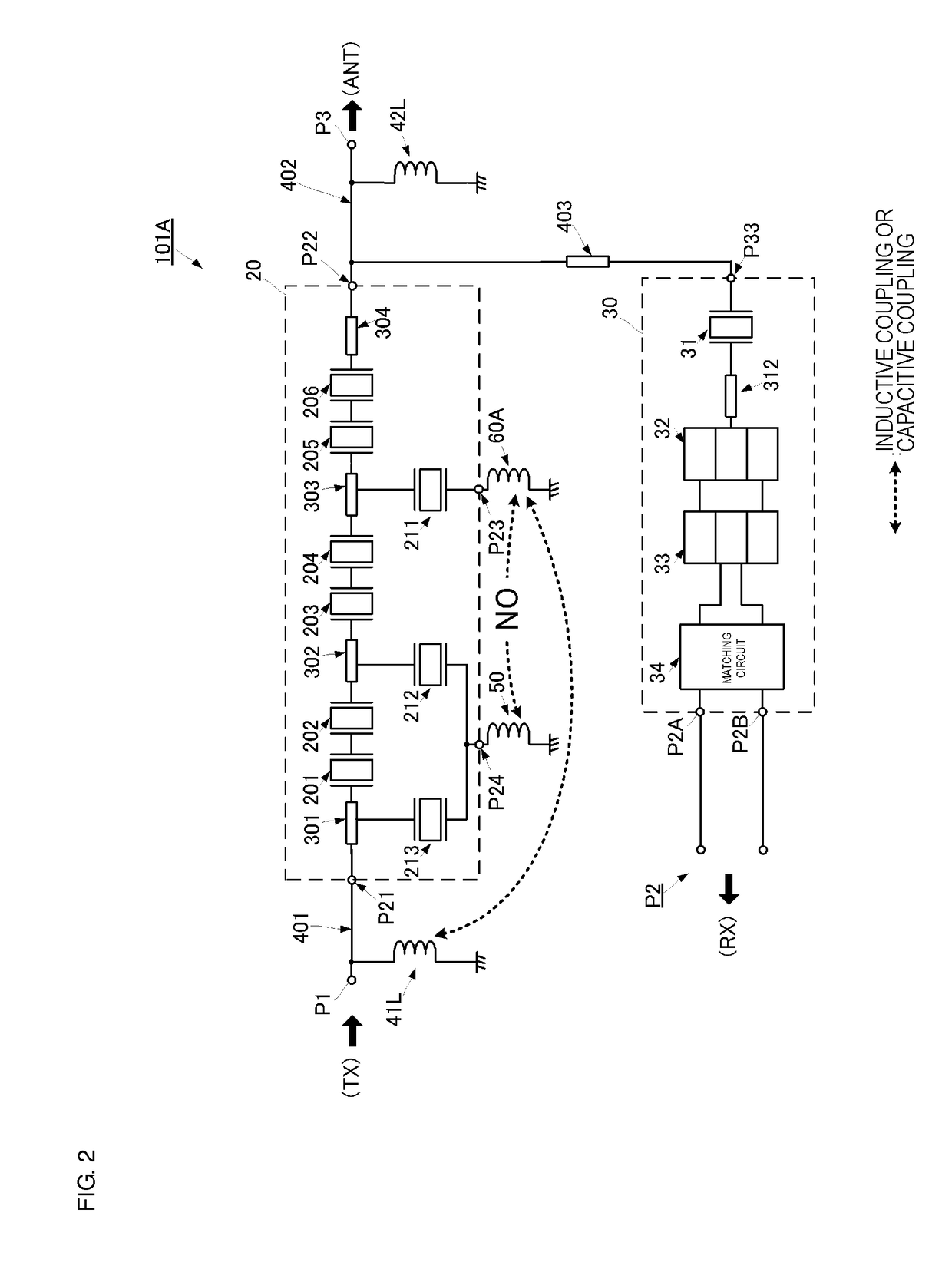
[0077]The duplexer 101A shown in FIG. 2 differs from the duplexer 101 shown in FIG. 1 in the following point. In the duplexer 101A, by the generation of electromagnetic field coupling between an inductor 60A and the inductor 41L, an adjustment path is provided, thus significantly improving isolation characteristics between the transmission and reception. That is, in the present example, the adjustment path that significantly improves the isolation characteristics includes the inductor 41L, the inductor 60A, the shunt connection terminal P23, the SAW resonator 211, and the connection conductor 303.

[0078]As shown in FIG. 2, the inductor 60A and the inductor 50 obstruct electromagnetic field coupling between the inductors 60A and 50, also in the duplexer 101A. For example, a ground is located between the inductor 60A and the inductor 50, or the inductor 60A and the inductor 50 are spaced by a distance therebetween longer than a distance between the inductor 60A and the inductor 41L. Ac...

third circuit example

[0080]The duplexer 101B shown in FIG. 3 differs from the duplexer 101 shown in FIG. 1 in the following point. In the duplexer 101B, by the generation of electromagnetic field coupling between an inductor 60B and the connection conductor 302, an adjustment path is provided, thus significantly improving isolation characteristics between the transmission and reception. That is, in the present example, the adjustment path that significantly improves the isolation characteristics includes the connection conductor 302, the inductor 60B, the shunt connection terminal P23, the SAW resonator 211, and the connection conductor 303.

[0081]As shown in FIG. 3, the inductor 60B and the inductor 50 obstruct electromagnetic field coupling between the inductors 60B and 50, also in the duplexer 101B. For example, a ground is located between the inductor 60B and the inductor 50, or the inductor 60B and the inductor 50 are spaced by a distance therebetween longer than a distance between the inductor 60B ...


PUM


Abstract

A transmission filter in a high frequency module includes serial arm resonators electrically connected in series to a serial arm electrically connecting a shared terminal and a transmission terminal, parallel arm resonators each electrically connected in series to each of parallel arms electrically connecting the serial arm and a ground, a first inductor electrically connected between the ground and a connection end electrically connecting at least the two parallel arm resonators of the parallel arm resonators, and a second inductor electrically connected between the ground and one parallel arm resonator different from the at least two parallel arm resonators of the parallel arm resonators. The second inductor is electromagnetic field coupled to at least one of an antenna side matching element, a transmission side matching element, and a portion of the serial arm in the transmission filter. The first and second inductors obstruct electromagnetic field coupling therebetween.

Description

CROSS REFERENCE TO RELATED APPLICATIONS[0001]This application claims the benefit of priority to Japanese Patent Application No. 2015-095948 filed on May 8, 2015 and is a Continuation Application of PCT Application No. PCT / JP2016 / 057913 filed on Mar. 14, 2016. The entire contents of each application are hereby incorporated herein by reference.BACKGROUND OF THE INVENTION1. Field of the Invention[0002]The present invention relates to a high frequency module including a transmission filter and a reception filter.2. Description of the Related Art[0003]A mobile apparatus or the like for wireless communication includes a transmission filter and a reception filter. The transmission filter passes only a component of a pass band of a transmission signal which is a high frequency signal, and attenuates components other than the component of the pass band. The reception filter passes only a component of a pass band of a reception signal received by an antenna, and attenuates components other th...

Claims


Application Information

Patent Timeline
Patent Type & Authority Applications(United States)
IPC IPC(8): H03H9/145H03H9/72H03H9/25
CPCH03H9/1455H03H9/14597H03H9/725H03H9/25H03H7/09H03H9/0542H03H9/0557H03H9/6483H03H9/02818H03H9/02433
Inventor KATO, MASANORIMIZOGUCHI, SHINYASUGAYA, YUKITERU
Owner MURATA MFG CO LTD
Why Eureka
Try Eureka