
Handheld electrocardiographic measurement device

Active Publication Date: 2018-03-08
MURATA MFG CO LTD
View PDF1 Cites 2 Cited by
  • Summary
  • Abstract
  • Description
  • Claims
  • Application Information

AI Technical Summary

Benefits of technology

The present invention provides handheld electrocardiographic measurement devices that can stably measure an electrocardiographic signal for a long period without getting tired or losing accuracy. The devices are designed to be held with both hands, and the fingers of both hands do not touch each other when the device is held for a long period, which prevents fatigue and allows for stable measurement. The devices can also simultaneously acquire a pulse wave signal, which increases the acquisition rate of biological information and allows for mutual complementation of heart rate and pulse wave transit time calculations.

Problems solved by technology

However, since this device is held with both hands from the left and right sides, for example, in a situation in which the device cannot be placed on a desk, when electrocardiographic measurement is continued for a long period (for example, about serval minutes), the hands holding the device get tired, and strain is applied to the hands and shoulders.
As a result, there is a fear that myoelectric noise will be easily included in the electrocardiographic signal.
However, if the touch of both hands is avoided, it may be difficult to grip the device.
Moreover, since the electrocardiographic signal detection device is held while being clamped (pinched) by, for example, thumbs and forefingers, strain is easily applied to the hands, and myoelectric noise is easily included.

Method used


Image

  • Handheld electrocardiographic measurement device
  • Handheld electrocardiographic measurement device
  • Handheld electrocardiographic measurement device

Examples


first preferred embodiment

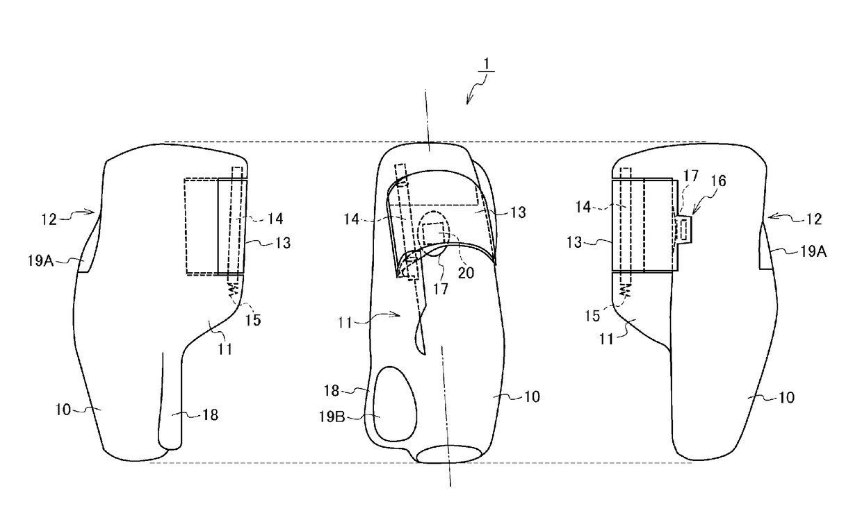
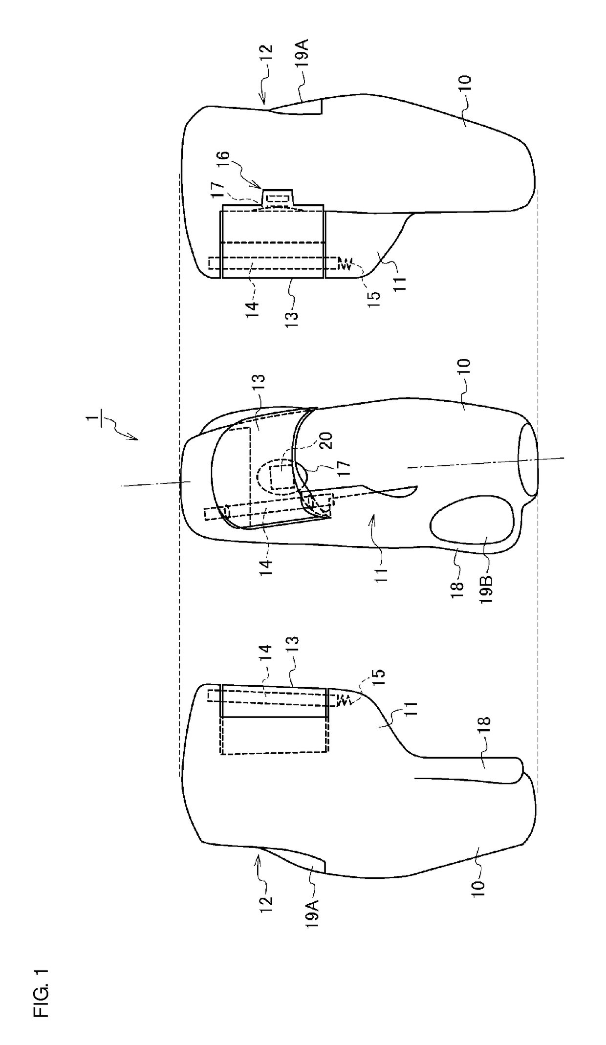
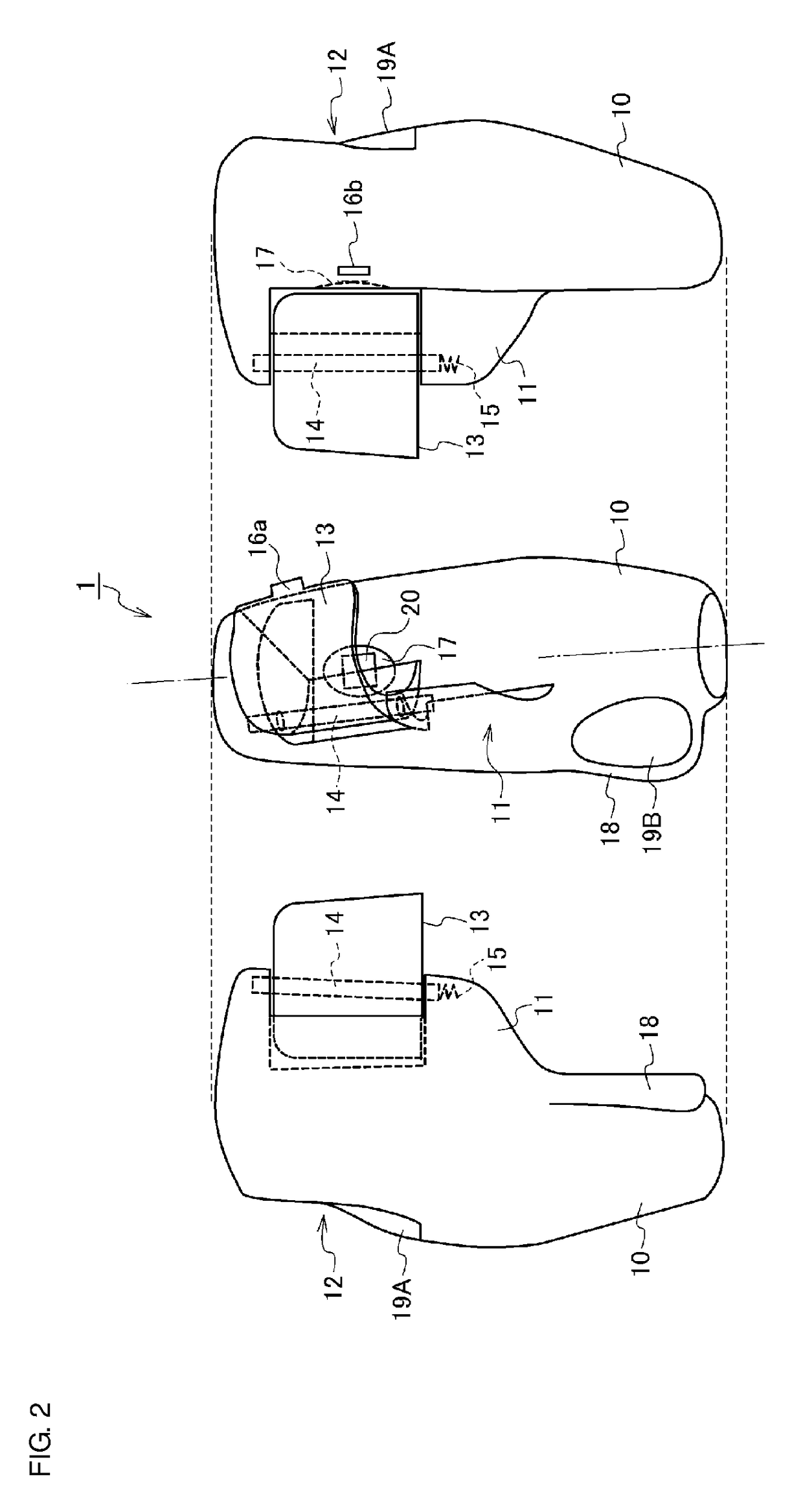
[0029]First, a structure of a handheld electrocardiographic measurement device 1 according to a first preferred embodiment of the present invention will be described with reference to FIGS. 1 to 4 in combination. FIG. 1 includes a front view and left and right side views illustrating an outward appearance of the handheld electrocardiographic measurement device 1 of the first preferred embodiment (in a state in which a shading cover is closed), and FIG. 2 includes a front view and left and right side views illustrating the outward appearance of the handheld electrocardiographic measurement device 1 (in a state in which the shading cover is open). FIG. 3 illustrates a state in which the handheld electrocardiographic measurement device 1 is held with hands (a measurement state). FIG. 4 is a block diagram showing a functional configuration of the handheld electrocardiographic measurement device 1.

[0030]The handheld electrocardiographic measurement device 1 is a handheld electrocardiogra...

second preferred embodiment

[0075]While the first electrocardiographic electrode 19A preferably is disposed on the back side of the body 10 in the handheld electrocardiographic measurement device 1 of the first preferred embodiment, a first electrocardiographic electrode 19C may preferably be disposed in the recess 17.

[0076]Accordingly, a handheld electrocardiographic measurement device 2 according to a second preferred embodiment of the present invention will be next described with reference to FIG. 5. Herein, descriptions of the same and similar structures to those of the first preferred embodiment are simplified or omitted, and differences are primarily described. FIG. 5 includes a front view and left and right side views illustrating an outward appearance of the handheld electrocardiographic measurement device 2 of the second preferred embodiment (in a state in which a shading cover is closed). In FIG. 5, the same or equivalent structural elements to those of the first preferred embodiment are denoted by t...


PUM


Abstract

A handheld electrocardiographic measurement device includes a substantially spheroidal body, a stopper projecting along an axial direction of the body to restrict a position of a thumb of one hand by abutting on a side surface of the thumb when a user grips the body with the one hand, a plate-shaped flange projecting from a side surface of the body in a direction orthogonal or substantially orthogonal to a projecting direction of the stopper, a first electrocardiographic electrode disposed on a back side of the body to touch a finger of the one hand when the body is gripped with the one hand, and a second electrocardiographic electrode disposed on a surface of the flange to touch a finger of the other hand when the flange is pinched by the other hand.

Description

CROSS REFERENCE TO RELATED APPLICATIONS[0001]This application claims the benefit of priority to Japanese Patent Application No. 2015-096115 filed on May 9, 2015 and is a Continuation Application of PCT Application No. PCT / JP2016 / 062888 filed on Apr. 25, 2016. The entire contents of each application are hereby incorporated herein by reference.BACKGROUND OF THE INVENTION1. Field of the Invention[0002]The present invention relates to a handheld electrocardiographic measurement device that acquires an electrocardiographic signal.2. Description of the Related Art[0003]In recent years, public interest in management, maintenance, and promotion of health has been growing. There is a demand that people can more easily obtain biological information, such as a pulse and an electrocardiographic information, in daily life. Japanese Unexamined Patent Application Publication No. 2013-226189 and Japanese Patent No. 5223967 each disclose an electrocardiographic measurement device to be held with bot...

Claims


Application Information

Patent Timeline
IPC IPC(8): A61B5/0404A61B5/0205A61B5/0408A61B5/00A61B5/04A61B5/332A61B5/296
CPCA61B5/0404A61B5/0205A61B5/0408A61B5/6826A61B5/04017A61B5/02427A61B5/332A61B5/25A61B5/316
Inventor SHIMUTA, TORU
Owner MURATA MFG CO LTD
Learn More