
Liquid nitrogen cooling sensor device container and liquid nitrogen cooling sensor device

Active Publication Date: 2014-11-27
JAPAN OIL GAS & METALS NAT CORP
View PDF2 Cites 2 Cited by
  • Summary
  • Abstract
  • Description
  • Claims
  • Application Information

AI Technical Summary

Benefits of technology

The liquid nitrogen cooling sensor device and equipment described in this patent can effectively reduce low-frequency noise by absorbing it through a damper effect, and it is easy to insert and pull out a probe from the liquid nitrogen. This allows for stable measurement over a long period of time.

Problems solved by technology

Here, low frequency noise, due to vibration caused by bubbles generated as the liquid nitrogen evaporates, adversely affects the measurement accuracy.
However, with this conventional method, large bubbles are prevented from being generated, but relatively small bubbles are generated, and thus the low frequency noise due to the vibration of the sensor still remains.
However, this conventional method has a problem that the rod cannot be freely inserted and pulled out while the liquid nitrogen is contained, and thus the sensor replacement and liquid nitrogen refilling cannot be easily performed.

Method used


Image

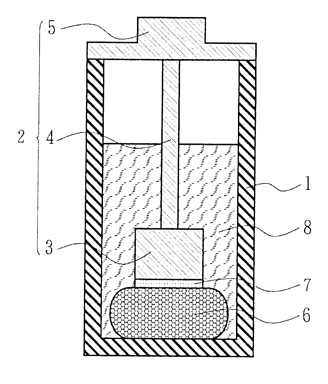
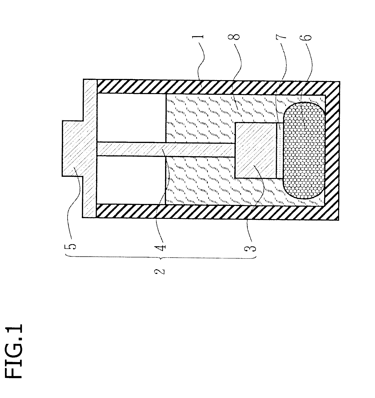
  • Liquid nitrogen cooling sensor device container and liquid nitrogen cooling sensor device
  • Liquid nitrogen cooling sensor device container and liquid nitrogen cooling sensor device
  • Liquid nitrogen cooling sensor device container and liquid nitrogen cooling sensor device

Examples


embodiment 1

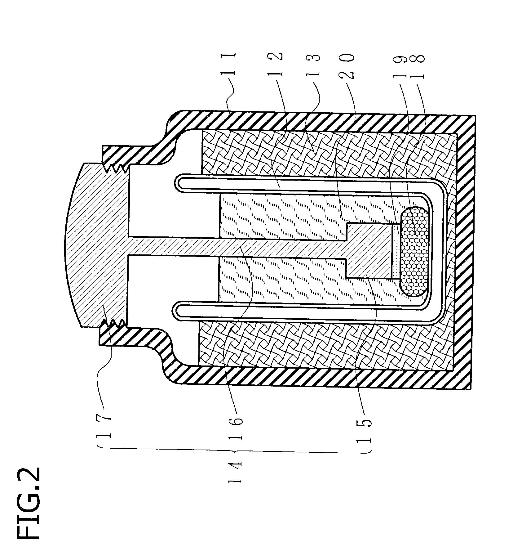
[0028]Next, the liquid nitrogen cooling sensor equipment of Embodiment 1 of the present invention will be described by referring to FIG. 2 and FIG. 3. FIG. 2 is a schematic cross-sectional view of the liquid nitrogen cooling sensor equipment of Embodiment 1 of the present invention. The liquid nitrogen cooling sensor equipment includes: an outer insulating container 11 made of plastic; a dewar 12 made of glass and having the double tube structure; a buffer 13 that protects / fixes the dewar 12; a probe 14 to be inserted in the dewar 12; and a fixing damper 18 that fixes the inserted probe 14 by the buffering effect.

[0029]The probe 14 is made of plastic, and includes: a sensor fixing unit 15 for fixing a superconducting sensor 19 with a pin; a probe rod 16; and a lid member 17. The wire of the superconducting sensor 19 is inserted through the probe rod 16 and the lid member 17. A lid screw is curved on a side circumference of the lid member 17, and is tightly coupled with a lid screw s...

embodiment 2

[0034]Next, a liquid nitrogen cooling sensor equipment of Embodiment 2 of the present invention will be described by referring to FIG. 4. FIG. 4 is a schematic cross-sectional view of the liquid nitrogen cooling sensor equipment of Embodiment 2 of the present invention. The liquid nitrogen cooling sensor equipment will be described as a single insulating container for simplifying the description, but generally has a double structure composed of the outer insulating container and the dewar.

[0035]In Embodiment 2 of the present invention, the PVA sponge is used as a fixing damper 27, and the fixing damper 27 is wrapped around a side surface of a sensor fixing unit 23 with a double-sided tape. Also in this case, the PVA sponge is sufficiently elastic at the temperature of the liquid nitrogen, and thus is compressed when a probe 22 is pressed into the liquid nitrogen containing insulating container 21, so that the sensor fixing unit 23 is fixed.

[0036]This structure is effective in a case...

embodiment 3

[0037]Next, a liquid nitrogen cooling sensor equipment of Embodiment 3 of the present invention will be described by referring to FIG. 5. FIG. 5 is a schematic cross-sectional view of the liquid nitrogen cooling sensor equipment of Embodiment 3 of the present invention. In this embodiment, a liquid nitrogen containing insulating container 31 is formed of Styrofoam.

[0038]In Embodiment 3 of the present invention, a fixing damper 37 is the UPIREX-FORM (registered trademark: UBE INDUSTRIES, LTD.) and covers a superconducting sensor 36 and a sensor fixing unit 33, as well as a part of a probe rod 34. In this embodiment, the fixing damper 37 includes two members 371 and 372 of a vertically divided structure. The superconducting sensor 36 and the sensor fixing unit 33 may be pressed into a recess portion formed in the members 371 and 372.

[0039]To form a large sensor equipment, a large liquid nitrogen containing insulating container 31 needs to be formed. It is difficult to form such a larg...


PUM


Abstract

The invention relates to a liquid nitrogen cooling sensor device container and liquid nitrogen cooling sensor equipment, and effectively reduces low-frequency noise while maintaining the ease with which a probe can be inserted in and removed from liquid nitrogen. Said invention comprises: a liquid nitrogen containing insulating container that contains liquid nitrogen; a sensor fixing member which has a distal end portion to which a sensor operating at a temperature of the liquid nitrogen is attached; and a fixing buffer member which is for fixing the sensor fixing member to the liquid nitrogen containing insulating container, wherein the fixing buffer member exerts a buffering effect in the liquid nitrogen.

Description

TECHNICAL FIELD[0001]The present invention relates to a liquid nitrogen cooling sensor device container and a liquid nitrogen cooling sensor equipment, and, for example, relates to a technique of reducing low frequency noise, produced by bubbles generated as the liquid nitrogen evaporates, for a sensor using a superconducting quantum interference device (SQUID), used in an underground resource exploration equipment and the like.BACKGROUND ART[0002]SQUIDs, using a high-temperature superconductor, are used in sensor devices such as an underground resource exploration equipment, a geomagnetic observation equipment , and a non-destructive testing device. Such a sensor device using the SQUID requires liquid nitrogen cooling and low noise conditions.[0003]Conventionally, in the liquid nitrogen cooling process in a SQUID underground resource exploration equipment, geomagnetic observation equipment , non-destructive testing device, and the like, where metal blocks should not be adjacently p...

Claims


Application Information

Patent Timeline
IPC IPC(8): F17C3/08G01R33/035
CPCG01R33/035F17C3/085
Inventor HATO, TSUNEHIROTANABE, KEIICHI
Owner JAPAN OIL GAS & METALS NAT CORP
Learn More