Differential refractive index measurement method, measurement device, and measurement program

Pending Publication Date: 2022-06-16
JASCO CORP
View PDF0 Cites 0 Cited by
  • Summary
  • Abstract
  • Description
  • Claims
  • Application Information

AI Technical Summary

Benefits of technology

[0052]According to the present invention, in the analysis device comprising the dual-flow type RI detection part, noise of the out

Problems solved by technology

Since the differential refractive index between the both liquids are measured while the reference liquid is enclosed

Method used


Image

  • Differential refractive index measurement method, measurement device, and measurement program
  • Differential refractive index measurement method, measurement device, and measurement program
  • Differential refractive index measurement method, measurement device, and measurement program

Examples


second embodiment

[0130]The adjustment method of the phase difference between pumps is described with reference to FIG. 12. The two graphs in FIG. 12 are actual measured values of a relation between the phase difference between pumps (horizontal axis) and the noise level (vertical axis) with respect to the two analysis devices of System A and System B. The inventors experimentally confirmed the existence of the phase difference of which the noise amplitude of the baseline becomes the minimum in the system configuration when the phase difference between the two liquid-sending pumps is changed sequentially. To what degree should the phase difference between pumps be set to minimalize the noise amplitude of the baseline depends on the system volume, the type of the solvent, and a system pressure; therefore, it is necessary to experimentally confirm for each system configuration.

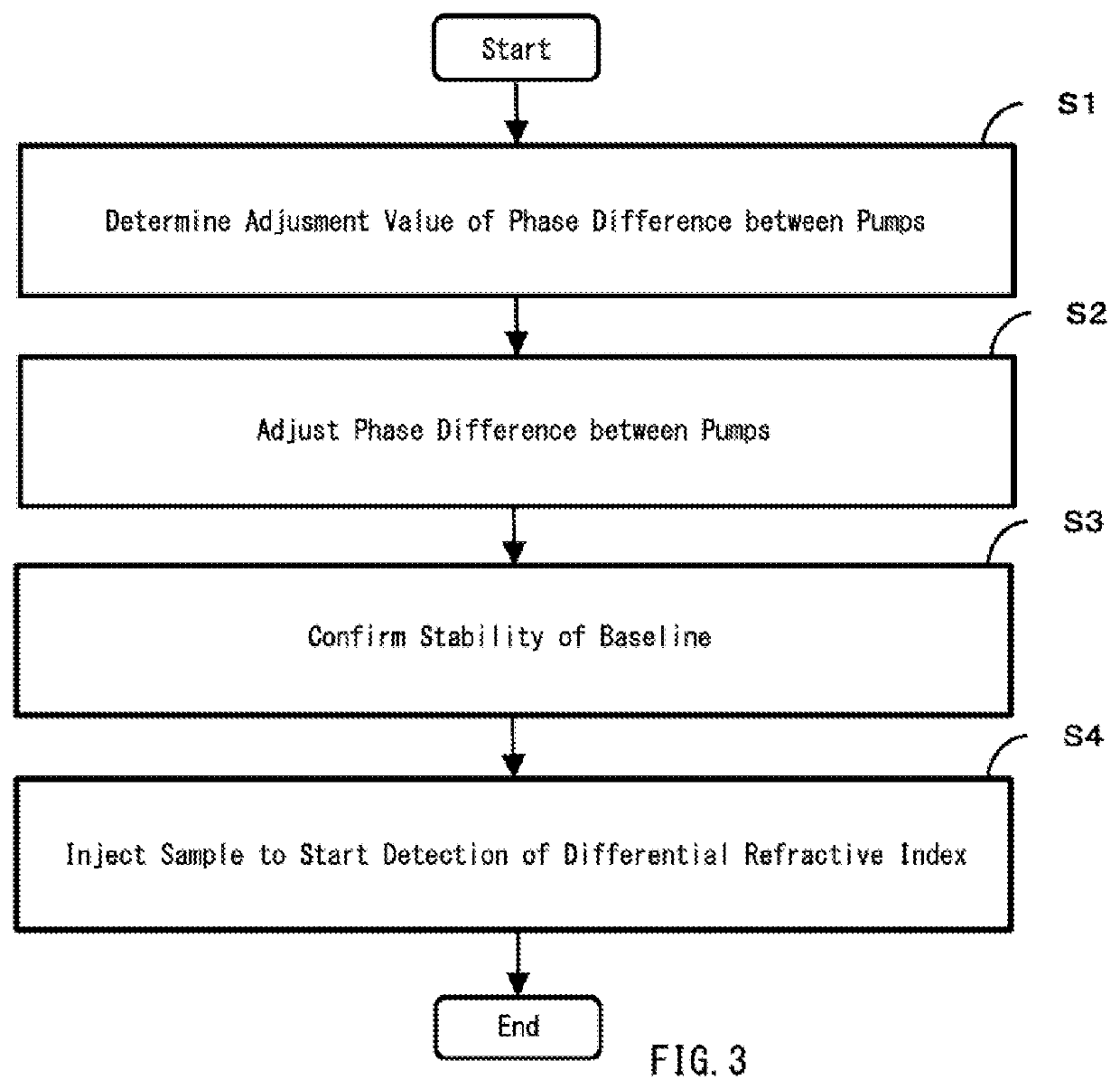
[0131]Thus, the adjustment method of the phase difference between pumps according to the second embodiment comprises steps of:...

first embodiment

[0134]Lastly, FIG. 14 depicts one example of the chromatogram when the chromatograph of the first embodiment is applied to GPC (dual-flow type). For comparison, FIG. 15 depicts one example of the chromatogram measured by a conventional GPC (single-flow type). The vertical axis is the differential refractive index, and the horizontal axis is retention time. In either case, tetrahydrofuran (THF) that does not contain a stabilizer was used as the mobile phase, and a polystyrene standard sample consisting of five components was used as the sample. The number of repetitions is respectively ten times.

[0135]It can be seen when the two are compared that, in the chromatogram of FIG. 14 according to the present embodiment, there is no drift in the baseline like the chromatogram of FIG. 15, a stable baseline is acquired, and repeatability of measurement is excellent. Even a mobile phase of an unstable composition such as THF that does not contain a stabilizer is used as the solvent, a stable b...


PUM

PropertyMeasurementUnit
Phaseaaaaaaaaaa
Noiseaaaaaaaaaa

Abstract

A method of reducing noise in an output signal of a differential refractive index detection part (RI detection part) of a dual-flow type with an analysis device having the RI detection part includes sending a sample liquid to a sample cell with a sample pump, sending a reference liquid to a reference cell with a reference pump, and detecting a change in direction of travel of light sequentially transmitted through the two cells with a light detector. Before starting RI measurement, a phase difference between the sample pump and the reference pump is adjusted so that a noise that occurs in an output signal of the light detector by propagation of pulsation from the sample pump within the sample cell and a noise that occurs in the output signal of the light detector by propagation of pulsation from the reference pump within the reference cell cancel each other.

Description

RELATED APPLICATION[0001]This application claims the priority of Japanese Patent Application No. 2019-072504 filed on Apr. 5, 2019, the disclosure of which is incorporated herein by reference in its entirety.TECHNICAL FIELD[0002]The present invention relates to measurement of a differential refractive index by an analysis device comprising a differential refractive index detector.BACKGROUND ART[0003]There is a conventional analysis device comprising a differential refractive index detection part (called as RI detection part) that uses a detection cell of which a sample cell and a reference cell are integrated, emits light to transmit both of a sample liquid in the sample cell and a reference liquid in the reference cell, and detects the difference in the refractive indexes between the both liquids based on the position of the transmitted light.[0004]In this analysis device, there are channels for sending the sample liquid and the reference liquid to cells of the RI detection part, a...

Claims


Application Information

Patent Timeline
IPC IPC(8): G01N30/74G01N30/32G01N21/41G01N1/14B01J20/291
CPCG01N30/74G01N30/32G01N2030/027G01N1/14B01J20/291G01N21/41G01N21/4133G01N2021/4146G01N2030/326
Inventor MOTEKI, TOMOHIROKUWAJIMA, MIKI
Owner JASCO CORP
Why Eureka
Try Eureka