Blower

a blower and blower technology, applied in the field of blowers, can solve the problems of reducing the efficiency of the blower, reducing the number of components of the blower, and reducing the axial fan

Inactive Publication Date: 2007-11-15
DENSO CORP
View PDF4 Cites 7 Cited by
  • Summary
  • Abstract
  • Description
  • Claims
  • Application Information

AI Technical Summary

Benefits of technology

[0008]In view of the foregoing problems, it is an object of the present invention to provide a blower having at least one axial fan rotated by a motor through a gear portion, which can restrict foreign materials from entering to the gear portion.

Problems solved by technology

However, in the blower having the axial fan, because the dynamic pressure of a rotating component part with rotation of the axial fan becomes loss, an axial component part with the rotation of the axial fan is reduced thereby reducing fan efficiency.
In this case, however, the number of components of the blower is increased, and the size and weight of the entire blower become large.
However, when the blower is mounted on a vehicle, foreign materials such as water, spattered stones and dust may be easily entered to the gear portions, thereby affecting rotation function of the gear portions.

Method used


Image

  • Blower
  • Blower
  • Blower

Examples


first embodiment

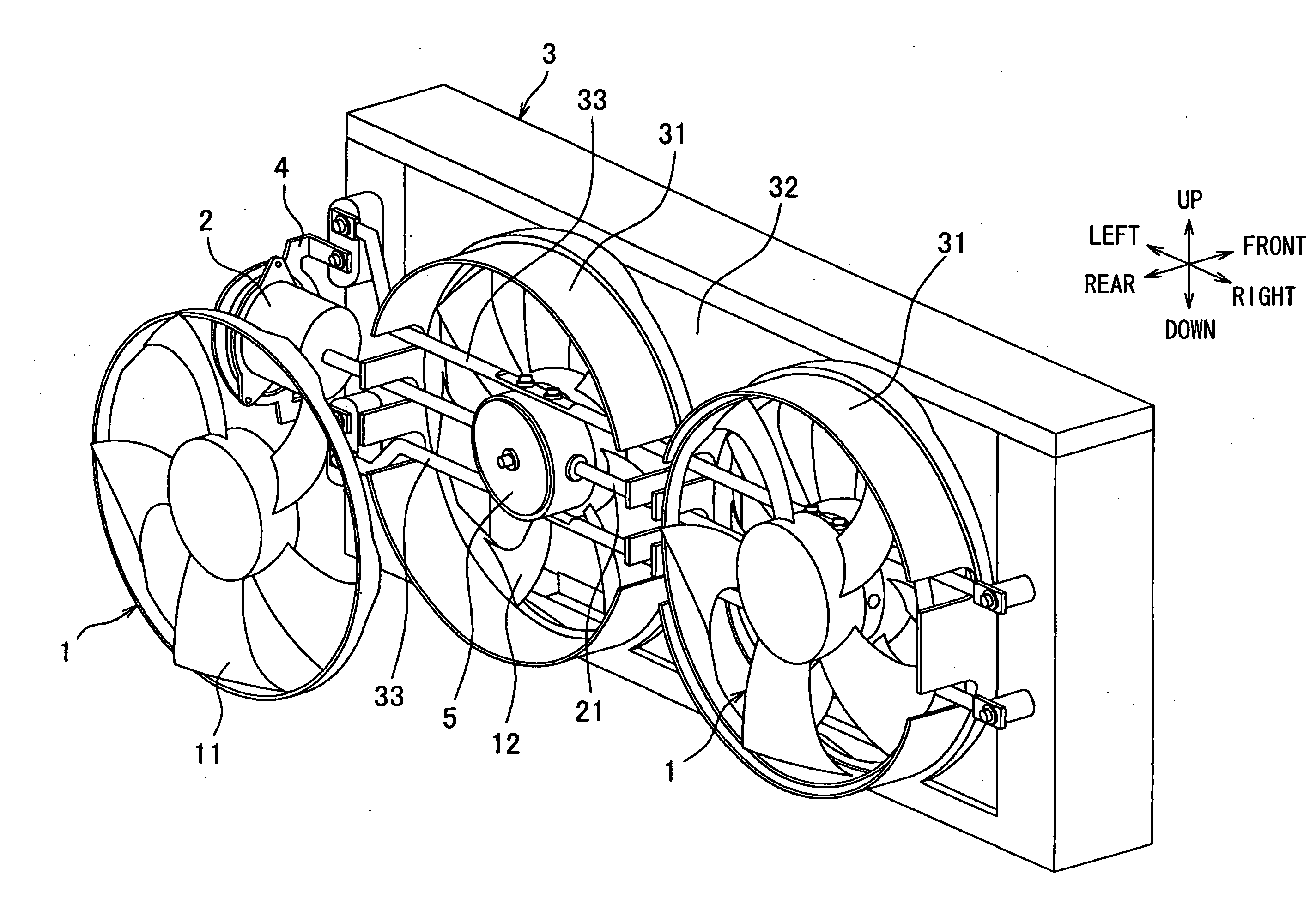
[0030]A first embodiment of the present invention will be now described with reference to FIGS. 1 and 2. In the first embodiment, a blower unit of the present invention is typically used for blowing cool air to a heat exchanger such as a radiator and a condenser (refrigerant radiator) mounted on a vehicle. Here, the radiator is a heat exchanger in which engine-cooling water (hot water) from an engine is heat-exchanged with air, and the condenser is a heat exchanger in which refrigerant circulating in a refrigerant cycle is heat-exchanged with air. In the first embodiment, the radiator is located in the vehicle at a vehicle rear side from the condenser, and the blower unit is located to blow air to the radiator and the condenser.

[0031]FIG. 1 is a disassembled perspective view showing contrarotating blowers 1 and a fan shroud 3 of the blower unit. In this embodiment, two contrarotating blowers 1 are arranged on a vehicle rear side of the heat exchanger (not shown). The two contrarotat...

second embodiment

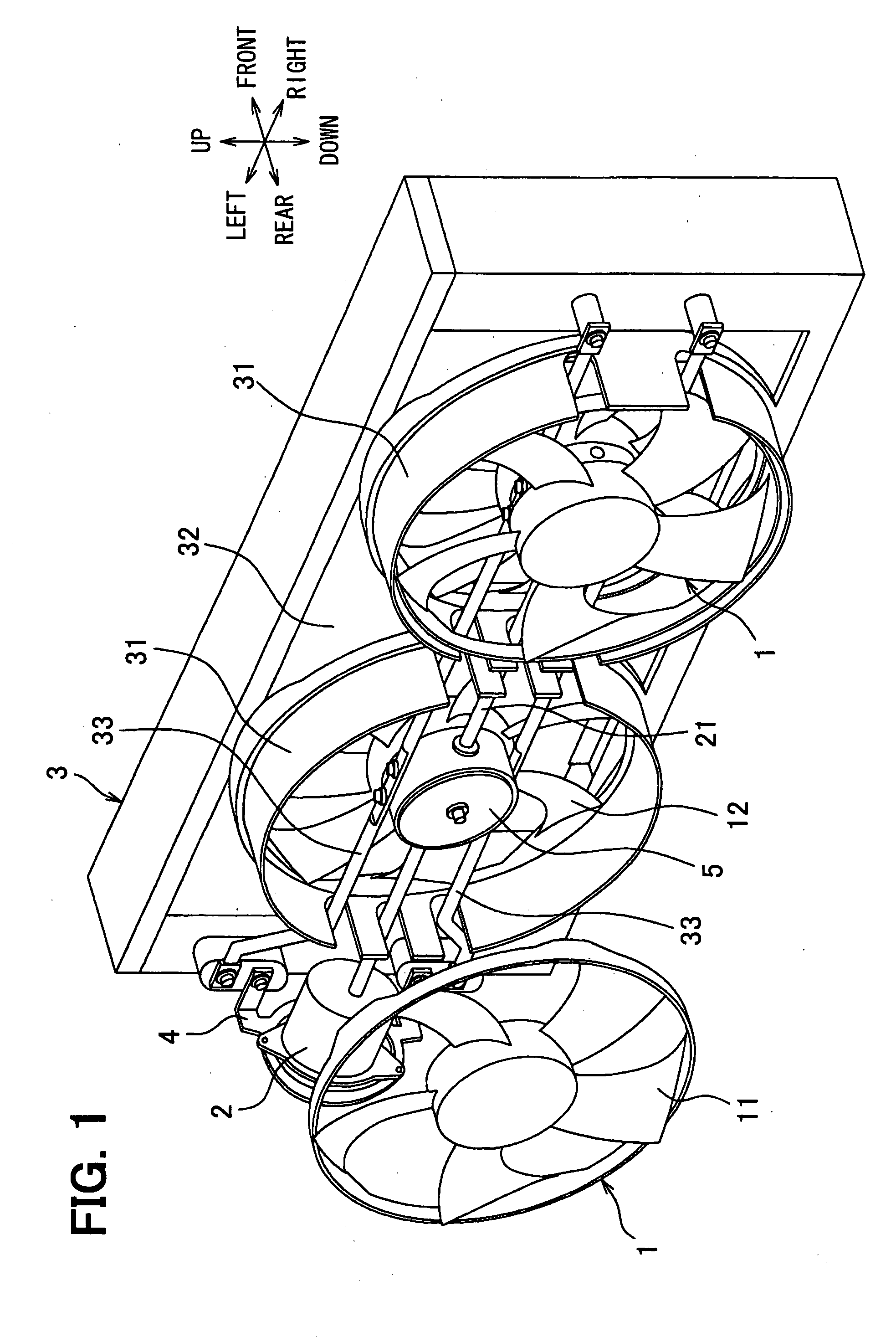
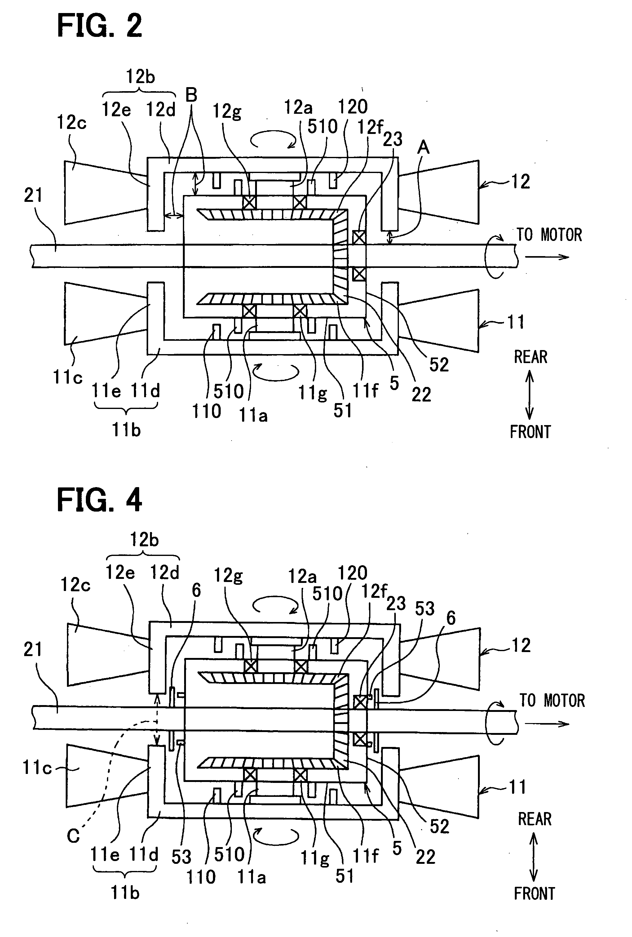
[0051]A second embodiment of the present invention will be now described with reference to FIGS. 3 to 8. In the second embodiment, the parts having the same functions as those of the first embodiment are indicated as the same reference numbers, and explanation thereof is omitted. FIG. 3 is a perspective view showing two contrarotating blowers 1 of the second embodiment and the fan shroud 3. In the second embodiment, a cover plate 6 (foreign material preventing member) is provided in the blower 1 so as to prevent foreign material from entering from the clearance between the boss portion 11b, 12b and the rotation drive shaft 21. In this embodiment, the cover plate 6 for preventing foreign material from entering is formed into approximately a circular shape. However, in FIGS. 3 and 5, a cut shape of the cover plate 6 cut in half in a vehicle up-down direction is indicated.

[0052]FIG. 5 is an enlarged view showing the part V indicated in FIG. 3, and FIG. 6 is a partial sectional top view...

third embodiment

[0062]A third embodiment of the present invention will be described with reference to FIG. 9. In the third embodiment, different parts different from the above-described first or second embodiment will be mainly described. In the third embodiment, the groove portion 21a described in the second embodiment is used as a first groove portion 21a, and a plurality of second groove portions 21b (e.g., two groove portions in this embodiment) are formed in the rotation drive shaft 21 at positions near the first groove portion 21a. In this embodiment, the first groove portion 21a and the second groove portions 21b are arranged at equal distance to have approximately the same shape.

[0063]The fan diameters of the axial fans 11, 12 or the dimension between the two gear boxes 5 may be different based on vehicle kinds or the like. Accordingly, if a single groove portion (first groove portion 21a) is formed, the single groove portion may need to be provided at different positions in accordance with...


PUM


Abstract

A blower includes two contrarotating axial fans located to be rotated reversely with each other in accordance with rotations of its rotation shafts arranged on an axial line. In the blower, a rotation drive shaft of a motor is coupled to the rotation shafts of the axial fans through a gear portion, and the gear portion is housed in a gear box. Each of the axial fans includes a boss portion having a recess shape opened in an axial direction of the axial fan, and a plurality of blades located radial outside of the boss portion. Furthermore, the axial fans are located such that the recess shapes of the boss portions are opposite to each other, and the gear box is located between the boss portions of the axial fans, and is covered by the boss portions from two sides in an air flow direction of the axial fans.

Description

CROSS REFERENCE TO RELATED APPLICATION[0001]This application is based on Japanese Patent Applications No. 2006-129760 filed on May 9, 2006 and No. 2006-211716 filed on Aug. 3, 2006, the contents of which are incorporated herein by reference in its entirety.BACKGROUND OF THE INVENTION[0002]1. Field of the Invention[0003]The present invention relates to a blower having at least one axial fan. For example, the present invention can be suitably applied to a contrarotating blower having two axial fans rotating reversely with each other.[0004]2. Description of the Related Art[0005]JP-A-2002-310097 describes a blower having an axial fan for sending cool air to a heat exchanger such as a radiator mounted on a vehicle. However, in the blower having the axial fan, because the dynamic pressure of a rotating component part with rotation of the axial fan becomes loss, an axial component part with the rotation of the axial fan is reduced thereby reducing fan efficiency.[0006]In order to increase ...

Claims


Application Information

Patent Timeline
Patent Type & Authority Applications(United States)
IPC IPC(8): F03D1/02
CPCF04D25/163F04D19/007F04D25/166
Inventor IWASAKI, TAKAHIROTAKEUCHI, KAZUHIROUSAMI, TAKUYA
Owner DENSO CORP
Why Eureka
Try Eureka