Flow amount control device

a flow amount and flow control technology, applied in the direction of valve housings, lubricant mounting/connection, separation processes, etc., can solve the problem of tension breaking of the connecting portion, and achieve the effect of not being radially detachabl

Active Publication Date: 2006-02-21
DENSO CORP
View PDF8 Cites 19 Cited by
  • Summary
  • Abstract
  • Description
  • Claims
  • Application Information

AI Technical Summary

Benefits of technology

[0006]It is an object of the present invention to provide a flow amount control device that restricts entering of foreign objects through fluid passages.
[0007]To achieve the above object, a flow amount control device is provided with the following. A housing whose peripheral wall is cylindrical is provided and it is penetrated by fluid passages. A valve member is provided as being contained in the housing and controlling a flow amount of fluid that passes through the fluid passages. A filter is provided as being circumferentially attached around the peripheral wall. The filter includes: a filtering element that covers the fluid passage for inhibiting foreign objects from entering the fluid passage; a supporting portion that extends circumferentially for supporting a peripheral edge of the filtering element; and a connecting portion that extends circumferentially for connecting between circumferential both ends of the supporting portion. The breadth of the connecting portion is narrower than that of the supporting portion. The filter is movable within a movable range according to a clearance between the filter and the peripheral wall. A first sealing portion is formed as surrounding an opening of the fluid passage in the peripheral wall, and a second sealing portion is formed as surrounding the filtering element in an inner surface of the supporting portion. The first sealing portion and the second sealing portion seal a gap between them by contacting with each other with being able to be slid within the movable range of the filter. This structure restricts entering of the foreign objects through the fluid passage by combining filtering function of the filtering element, with sealing function of the contact between the above first and second sealing portions, even when the filter moves according to the clearance with the peripheral wall.
[0008]It is preferable that the flow amount control device is further provided with the following. The connecting portion of the filter can be divided into a first and a second division portions at a circumferentially intermediate point. The first division portion has a first convex portion and the second division portion has a first concave portion, and one of the division portions has a second convex portion and the other has a second concave portion. The first convex portion and the first concave portion are hooked with each other, with being unable to be circumferentially detached, and the second convex portion and the second concave portion are hooked with each other, with being unable to be radially detachable. This structure enables the filter to be easily attached around the peripheral wall of the housing and to be hardly detached from the peripheral wall. This results in securely obtaining an effect of restricting entering of the foreign objects through the fluid passage.

Problems solved by technology

Furthermore, when the connecting portion of the filter is pushed upon the peripheral wall due to the move of the filter, the connecting portion may be broken with tension.

Method used


Image

  • Flow amount control device
  • Flow amount control device
  • Flow amount control device

Examples


Embodiment Construction

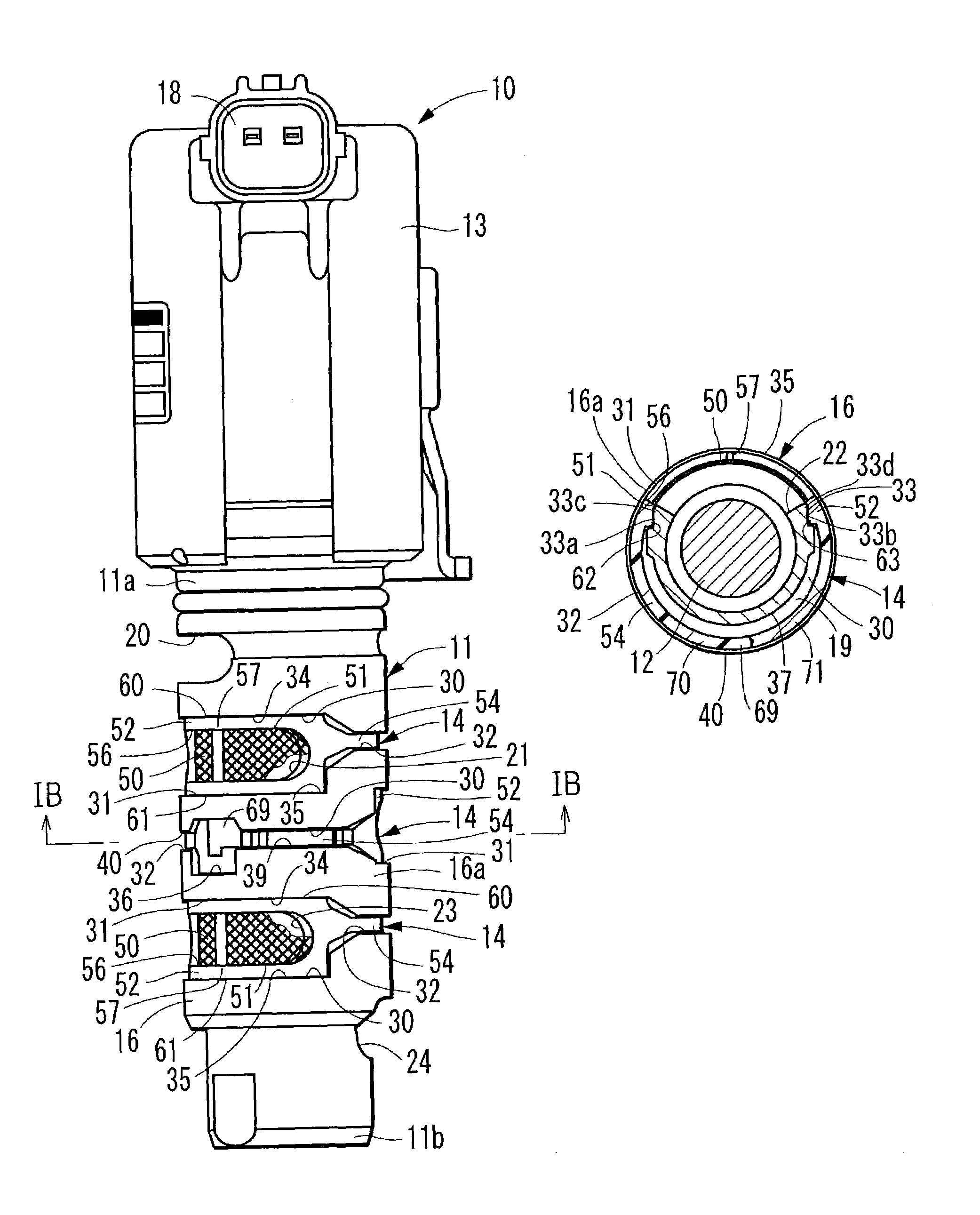
[0019]A flow amount control device 10 according to an embodiment of the present invention is shown in FIG. 1A. The flow amount control device 10 is assembled in an engine. A valve timing adjusting device is assembled in the engine for adjusting valve timing of a suction or exhaust valve by oil pressure control. The flow amount control device 10 controls an amount of operating oil with which the valve timing adjusting device is provided.

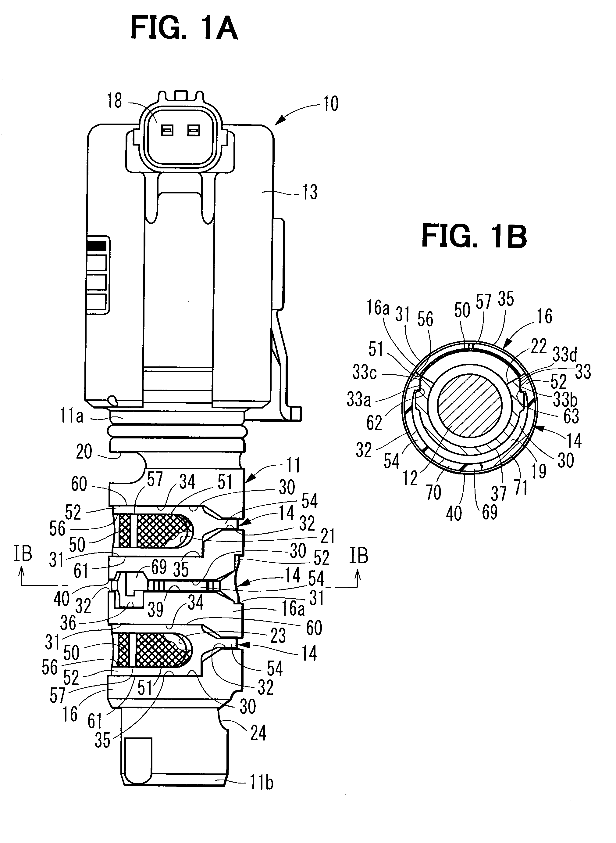
[0020]The flow amount control device 10 includes a sleeve 11 as a housing, a spool 12 as a valve member, an electromagnetic drive device 13, a filter 14, and the like. The sleeve 11 shown in FIGS. 1A, 1B, 2, 3A, 3B, 5A is formed in a generally cylindrical shape by die-casting of aluminum. As shown in FIGS. 3A, 3B, the sleeve 11 is inserted within an insertion bore 4 provided in an assembling member 2 of the engine along with the filter 14. The sleeve 11 includes fluid passages 20 to 24 that penetrate a peripheral wall 16 of the sleeve 11. The fluid pa...


PUM

PropertyMeasurementUnit
sizeaaaaaaaaaa
sizeaaaaaaaaaa
lengthaaaaaaaaaa

Abstract

A filter is annularly attached around a peripheral wall of a housing. The filter is composed of a filtering element that covers a fluid passage for inhibiting foreign objects from entering, a supporting portion for supporting the filtering element, and a connecting portion for connecting between both ends of the supporting portion. The connecting portion is narrower than the supporting portion. The filter is movable radially in two directions according to a clearance between the filter and the housing. A contact portion is formed, with being able to be slid within a movable range of the filter, between an outer surface portion of the peripheral wall that surrounds an opening of the fluid passage and an inner surface portion of the filter that surrounds the filtering element.

Description

CROSS REFERENCE TO RELATED APPLICATIONS[0001]This application is based on and incorporates herein by reference Japanese Patent Application No. 2002-165494 filed on Jun. 6, 2002.FIELD OF THE INVENTION[0002]The present invention relates to a flow amount control device that restricts entering of foreign objects through fluid passages.BACKGROUND OF THE INVENTION[0003]A known flow amount control device has a housing whose peripheral wall is penetrated by fluid passages, and a valve member contained within the housing, and controls an amount of fluid flowing among the fluid passages by reciprocating the valve member. The flow amount control device includes a filter for inhibiting foreign objects from entering an inside of the housing through the fluid passages.[0004]In JP-2001-173806A, a flow amount control device (fluid control valve) includes a filter that is fitly attached annularly around a peripheral wall of a housing. The filter includes: a filtering element that covers a fluid pass...

Claims


Application Information

Patent Timeline
Patent Type & Authority Patents(United States)
IPC IPC(8): E03B3/18F01M11/03F16K51/00F16K11/07F16K31/06
CPCF16K27/048F16K11/0712F16K31/0613F01M11/03F01L2001/34436F01L2001/3444Y10T137/8122Y10T137/8085
Inventor OKADA, MOTOHIROMOHRI, MITOMU
Owner DENSO CORP
Why Eureka
Try Eureka