Vehicle side structure

a side structure and vehicle technology, applied in the direction of superstructure connections, belt retractors, transportation and packaging, etc., can solve the problems of increasing the number of components, deteriorating etc., to achieve high rigidity, stress concentration, and increase the rigidity of the lower section of the pillar inner panel 32

Active Publication Date: 2018-03-08
TOYOTA JIDOSHA KK
View PDF0 Cites 12 Cited by
  • Summary
  • Abstract
  • Description
  • Claims
  • Application Information

AI Technical Summary

Benefits of technology

[0045]Next, actions and effects of the above-described embodiment will be described.
[0046]In the present embodiment, as shown in FIG. 1 as an example, the extended-out section 42 of the reinforcing section 40 is extended out integrally toward an outer side in the vehicle width direction from an entire periphery of a peripheral edge of the opening 32F of the pillar inner panel 32. As a result, stress concentration at the peripheral edge of the opening 32F of the pillar inner panel 32 is suppressed, and rigidity of the lower section of the pillar inner panel 32 is increased. In addition, the lower section of the reinforcing section 40 is joined to the upper section of the rocker 18. Therefore, even if a load attempting to deform an opening 32F side in the pillar inner panel 32 acts during a collision, and so on, the load can be transmitted to the rocker 18, hence deformation of the opening 32F side in the pillar inner panel 32 is effectively suppressed.
[0047]Moreover, the lower wall section 42B of the extended-out section 42 makes surface contact with the upper surface section 20U of the rocker inner panel 20. Therefore, even if a load attempting to deform the opening 32F side in the pillar inner panel 32 acts, the load is transmitted to the upper surface section 20U of the rocker inner panel 20 via the extended-out section 42. Therefore, deformation of the opening 32F side in the pillar inner panel 32 is more effectively suppressed.
[0048]In addition, the end section on an outer side in the vehicle width direction of the lower wall section 42B of the extended-out section 42 is joined to the upper surface section 20U in the rocker inner panel 20 along a connecting part of the upper surface section 20U and the upper end flange section 20A in the rocker inner panel 20. Here, the connecting part of the upper surface section 20U and the upper end flange section 20A in the rocker inner panel 20 is a part of relatively high rigidity in the rocker inner panel 20. Therefore, deformation of the lower wall section 42B of the extended-out section 42 and furthermore deformation of the lower section of the pillar inner panel 32 is even more effectively suppressed.
[0049]Furthermore, the ridge section 20X is formed along the vehicle front-rear direction in the vertical wall-like inner wall section 20E configuring the end section side on an inner side in the vehicle width direction in the rocker 18, and the ridge section 20X configures a part of relatively high rigidity in the inner wall section 20E. Moreover, since the lower end section (a pillar inner panel lower end section according to technology of the present disclosure) of the pillar inner panel 32 is joined to the inner wall section 20E of the rocker 18 along such a high-rigidity ridge section 20X, deformation of the lower end section of the pillar inner panel 32 joined to the rocker 18 is more effectively suppressed.
[0050]As described above, due to the vehicle side structure of the present embodiment, a configuration having the retractor mounting-dedicated opening 32F formed in the lower section of the pillar inner panel 32 makes it possible for rigidity of the lower section of the pillar inner panel 32 to be improved even in a case in which a separate reinforcing member is not provided.

Problems solved by technology

Incidentally, in cases in which the opening of the above-described kind is formed in the lower section of the pillar inner panel, rigidity of the lower section of the pillar inner panel ends up deteriorating.
On the other hand, in a structure where a separate reinforcing member is attached to the lower section of the pillar inner panel, there is a disadvantage that the number of components increases.

Method used


Image

  • Vehicle side structure
  • Vehicle side structure
  • Vehicle side structure

Examples


first embodiment

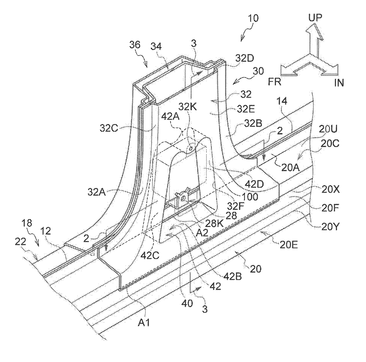
[0024]A vehicle side structure according to a first embodiment of technology of the present disclosure will be described using FIGS. 1 to 3. Note that regarding arrows FR, UP, and IN appropriately indicated in these drawings, the arrow FR indicates a front side of a vehicle, the arrow UP indicates an upper side of the vehicle, and the arrow IN indicates an inner side in a vehicle width direction.

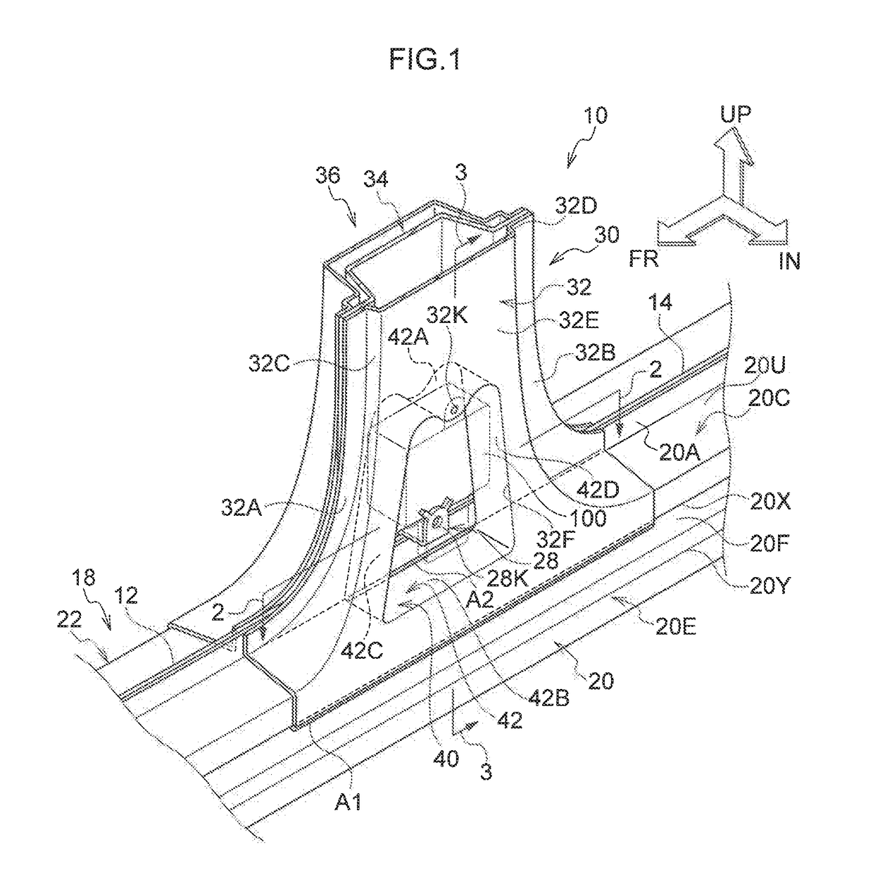
[0025]FIG. 1 shows an overall configuration of the vehicle side structure according to the present embodiment in a perspective view of a state of being seen from an inner side in the vehicle width direction. In addition, FIG. 2 shows an enlarged plane cross-sectional view enlarging a state of a section taken along the line 2-2 of FIG. 1; and FIG. 3 shows an enlarged vertical cross-sectional view enlarging a state of a section taken along the line 3-3 of FIG. 1.

[0026]As shown in FIG. 1 as an example, a front door opening 12 opened / closed by an unillustrated front side door is formed on a fron...

second embodiment

[0051]Next, a vehicle side structure according to a second embodiment of technology of the present disclosure will be described using FIGS. 4 to 6. FIG. 4 shows an overall configuration of the vehicle side structure according to the present embodiment in a perspective view of a state of being seen from an inner side in the vehicle width direction. In addition, FIG. 5 shows an enlarged plane cross-sectional view enlarging a state of a section taken along the line 5-5 of FIG. 4; and FIG. 6 shows an enlarged vertical cross-sectional view enlarging a state of a section taken along the line 6-6 of FIG. 4.

[0052]Note that the present embodiment substantively has a similar configuration to the first embodiment excluding a configuration of a rocker 50 and a configuration of a reinforcing section 60. Hence, in the present embodiment, configuring sections substantively similar to those of the first embodiment will be assigned with identical symbols to those assigned in the first embodiment, an...


PUM


Abstract

A vehicle side structure includes: a rocker disposed along a vehicle front-rear direction at a lower section of a vehicle side; and a pillar disposed along a vehicle up-down direction at the vehicle side whereby a lower end section of the pillar is joined to the rocker, the pillar including: a pillar inner panel disposed at a vehicle interior inner side, and a pillar outer panel disposed at a vehicle interior outer side of the pillar inner panel, and the pillar having an opening, formed at a lower section of the pillar inner panel, the pillar inner panel having formed therein a reinforcing section including an extended-out section that extends out toward an outer side in a vehicle width direction from an entire periphery of a peripheral edge of the opening, and a lower section of the reinforcing section being joined to an upper section of the rocker.

Description

CROSS-REFERENCE TO RELATED APPLICATION[0001]This application claims priority under 35 USC 119 from Japanese Patent Application No. 2016-175909 filed Sep. 8, 2016, the disclosure of which is incorporated by reference herein.BACKGROUNDTechnical Field[0002]Technology of the present disclosure relates to a vehicle side structure.Related Art[0003]In order to mount a device such as, for example, a retractor (a seat belt winding device) of a seat belt device, or the like, in a lower section of a pillar inner panel of a vehicular pillar, a structure having an opening formed therein, is known (refer to, for example, Japanese Patent Application Laid-Open Publication No. 2016-22909 and Japanese Patent Application Laid-Open Publication No. 2016-97878).SUMMARY[0004]Incidentally, in cases in which the opening of the above-described kind is formed in the lower section of the pillar inner panel, rigidity of the lower section of the pillar inner panel ends up deteriorating. On the other hand, in a s...

Claims


Application Information

Patent Timeline
Patent Type & Authority Applications(United States)
IPC IPC(8): B62D25/04B62D25/02B60R22/34
CPCB62D25/04B62D25/025B60R2022/3402B62D27/023B60R22/34B62D25/00B60R22/24
Inventor KAMIMURA, SHINYAMIURA, TAKUYA
Owner TOYOTA JIDOSHA KK
Why Eureka
Try Eureka