
Stiffeners for utility trailer structural panels

a technology for supporting structures and utility trailers, applied in the directions of superstructure connections, transportation and packaging, doors, etc., can solve the problems of unsatisfactory approach, early failure of the system, and large tooling and handling costs, and achieve the effect of effective addressing edge stress concentration and cost-effective manufacturing

Inactive Publication Date: 2010-06-22
UTILICORP L C
View PDF47 Cites 10 Cited by
  • Summary
  • Abstract
  • Description
  • Claims
  • Application Information

AI Technical Summary

Benefits of technology

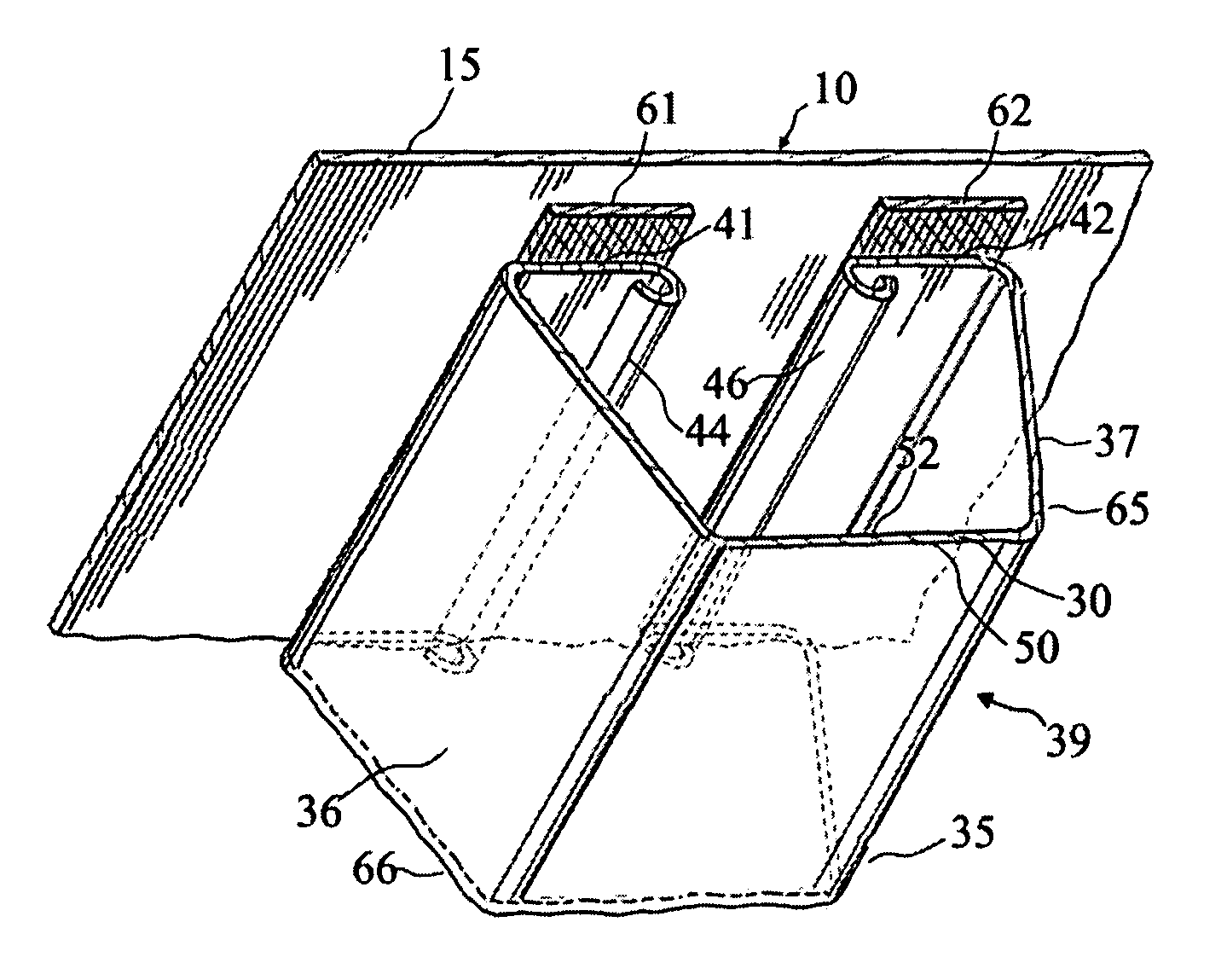
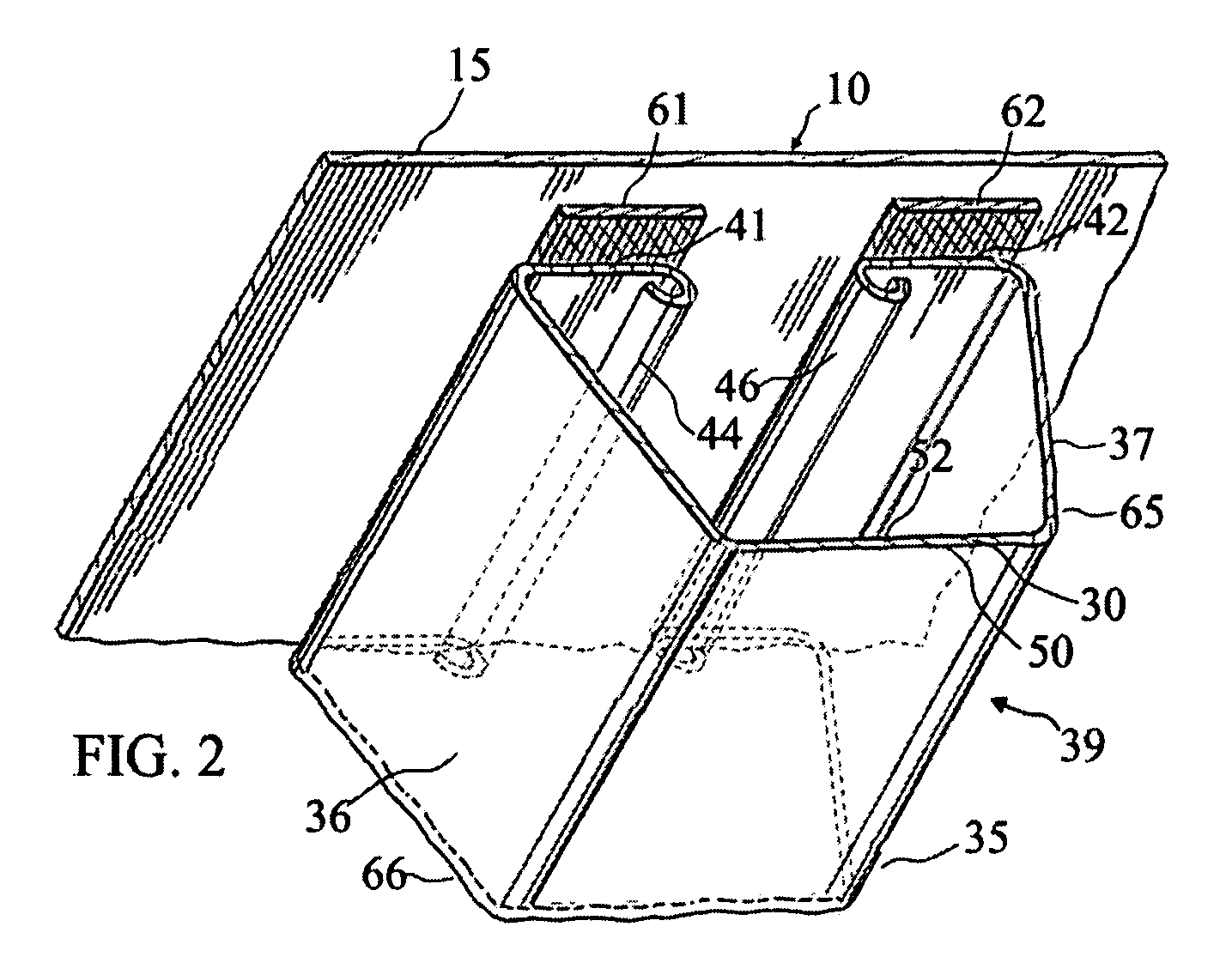
"The present invention is a new utility trailer structural panel stiffener that solves problems of the prior art. It is made of a thinner material to reduce stress, meets new requirements, and is resistant to buckling and rolling. It also addresses edge stress concentrations and is cost-effective to manufacture. The stiffener has a central flange, a web, and mounting flanges with tubular beads for reinforcement. The panel skin has parallel elongate stiffeners aligned to its longitudinal axis. The stiffener's tubular bead has a closed end and a curled end portion within an enclosed area for reinforcement. The invention provides stiffeners that are strong while being lightweight."

Problems solved by technology

Over the past several years, utility trailer design engineers have been challenged to address ever-higher payload requirements.
The use of thicker material has not only lead to greater tooling and handling costs, but also has had the effect of simultaneously creating other major problems.
However, an incompatibility occurs when relatively thick, stiffer sections, i.e., stiffeners made of 0.055 inch min. to 0.070 inch min. material are joined or fastened to thinner, less stiff skin made of 0.027 inch min. to 0.050 inch min. mater
ffener. This may result in early failure of the system, such as by buckling of the stiffener or of t
he skin. This is due to in-plane loads that result from the constraint that the stiffener imposes on the adjacent skin as the loads are i
e panel skin. However, this approach is undesirable because by increasing the number of parts, and increases the complexity and cost
Another drawback to additional fasteners is that it requires substantially more tooling and installation time.
First, the thinner materials used in these traditional stiffener configurations make these stiffener sections more susceptible to edge stress concentrations. The conventional C-channel, Z-shaped, and hat-shaped stiffeners have a “blade edge.”This edge is very susceptible to imperfections in the sheet material along this edge as well as to damage during manufacture, shipping / handling and installation. These imperfections along the blade edge become stress concentration points or focal points at which failure of the stiffener and adjacent fasteners or adhesive layers can initiate. Even the most perfect, smooth edge of the conventional stiffener will experience a very localized point of high stress gradient due to the characteristic edge stress concentration associated with open sections under bending loads.
It is significant that this stress concentration may be made worse by the presence of any relatively small local edge imperfections, even those on the order of size of the thickness of the stiffener material itself.
Where multiple imperfections occur together, they may all compound together to further increase the stress concentration effect, and thus lower the load level at which failure is initiated.
Second, all the above conventional stiffeners, when manufactured out of relatively thin sheet materials, are more susceptible to buckling due to the reduced thickness.
Buckling is an instability in a part of the stiffener associated with local compressive or shear stresses.
Buckling can precipitate section failure of the stiffener.
This in turn causes a stress concentration in the adjacent adhesive bond line or fasteners of the panel skin near the buckled stiffener section, which may cause the stiffened panel system to fail.
Finally, some thinner conventional stiffeners can experience “rolling” when placed under load.
Rolling may be caused when the shear stresses within the stiffener result in a net torque about the centroid of the thin walled cross-section thus causing the cross-section to twist, possibly making the stiffener unstable.
Another cause of rolling is the curvature of the panel itself that is induced by in-plane or pressure loads that are imposed upon the stiffened panel.
Additionally, increasing the cross-sectional flange length caused difficulty in accessing the fastener areas used in mounting the C-channel to the stiffened panel.

Method used


Image

  • Stiffeners for utility trailer structural panels
  • Stiffeners for utility trailer structural panels
  • Stiffeners for utility trailer structural panels

Examples


embodiment 110

[0061]FIGS. 5A and 5B show two embodiments of alternative tubular edge features to that of FIG. 5. Each of these two embodiments is directed to a bead or curl in which the outer diameter to thickness ratio of the tubular edge is larger than about 13. In these cases, additional stiffening of the tubular edge may be desired. As shown in embodiment 110, a smaller elliptical curl 107 inside the tubular edge feature 54A is shown in FIG. 5A, and includes a “curl flange”116 with associated thickness t, radius R11, and angle theta 11 in order to further stabilize tubular edge 54A. For ratios of radius R11 to thickness of 3.5 or less, and for angles theta 11 between 30 and 120 degrees in the positive or negative direction, a special strengthening effect is obtained which causes the curl flange 116 to act together with tubular edge 54A so that the entire edge is substantially strengthened and stabilized against warping. This added stabilization is thus a very useful extension of the capabilit...

embodiment 113

[0062]As an alternative to the curl within a curl of FIG. 5A, FIG. 5B shows embodiment 113 having a lip 114 of length L11 that may be applied to the free edge of the curl 54B, such as is shown in FIG. 5B. In this case the angle theta 12 is between 30 and 120 degrees for best results, and the length L11 of lip 114 is between 1 / 5 and 4 / 5 of the average of edge tube dimensions L12 and L13 for best results. Longer lips may be used, but usually with limited additional benefits over the benefits of the range given.

[0063]A typical utility trailer panel may be of dimensions being 102 inches by 48 inches. The stiffeners are preferably secured to the panel, each being made of steel and having a thickness of 0.036 inch with W1 and W2 being 0.6 inch and W3 being 1.2 inches. Diameter d is 7 / 32 inch and diameter d1 is 7 / 32 inch.

[0064]Referring now to the perspective view of FIG. 6, a stiffener section of the prior art is shown having blade edges along the ends of the section. The relative lack of...


PUM


Abstract

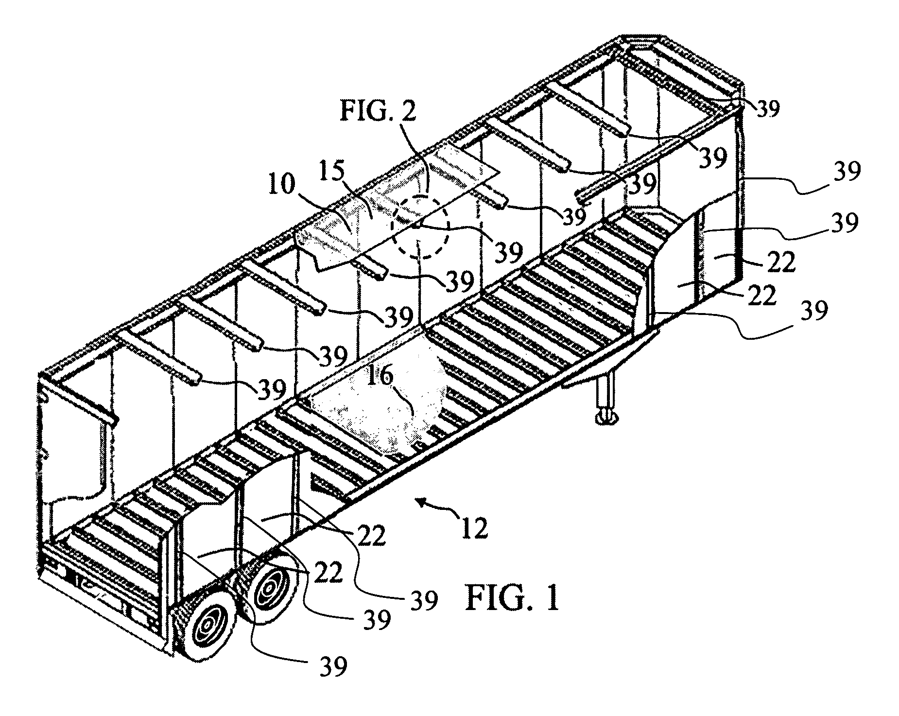
A utility trailer structural panel (10) of the skin-stiffener type has a skin (15) supported by uniformly spaced stiffeners or roof bows (39). Stiffeners or roof bows (39) are secured to panel skin (15) and extend outwardly from the associated panel skin (15). Each stiffener (39) has central flange (35) from which extend webs (36, 37) to mounting flanges (41, 42). Mounting flanges (41, 42) have free edges and respective beads or curls (44, 46) formed thereon for stabilizing of flanges (41, 42) to improve load transfer at the interface between the roof bows (39) and the skin (15).

Description

RELATED CASE[0001]The present application claims priority from U.S. Ser. No. 60 / 833,382 filed Jul. 26, 2006.FIELD OF THE INVENTION[0002]This invention relates generally to a reinforcing support structure for utility trailer structural panels of the skin-stiffener type, and more particularly to stiffeners mounted on utility trailer panels.BACKGROUND OF THE INVENTION[0003]Stiffeners such as roof bows have long been used in the transportation industry as basic structural elements that serve to reinforce the sides and roof of vehicle cargo areas. These structures are commonly installed adjacent to wall members as local reinforcements. Roof bow sections are often formed from high yield strength steel in an effort to increase strength and buckling resistance of the cross sections under various types of loads, including vibration, weather-related (such as snow and ice), and contact loads associated at times with fork lifts and other equipment, as well as the cargo itself, which may impinge...

Claims


Application Information

Patent Timeline
Patent Type & Authority Patents(United States)
IPC IPC(8): B60J5/00
CPCB62D33/04
Inventor OCHOA, CARLOS M.
Owner UTILICORP L C
Learn More