Link for endless track belt

a technology of endless track and link, which is applied in the direction of driving chains, hinges, transportation and packaging, etc., can solve the problems of weakened strength, increased process number, and increased welded parts, so as to reduce the stress concentration in such a region, reduce the strength of the link (100), and reduce the weight of the link (100)

Inactive Publication Date: 2009-09-17
TOPY INDUSTRIES
View PDF6 Cites 10 Cited by
  • Summary
  • Abstract
  • Description
  • Claims
  • Application Information

AI Technical Summary

Benefits of technology

[0035]According to the present invention having the above-mentioned constructions, since a reinforcing part (7) is formed in the region in the window area (5) in which the region a stress concentration can be generated and the reinforcing part (7) extends in the direction apart from a track shoe (in the direction indicated with the arrow Z in FIG. 1), the stress concentration in such the region is reduced and the strength of the link (100) improves in proportion to a reduction value of the stress concentration.
[0036]Consequently, by the present invention, if the strength of the link is the same, a weight of the link (100) can be reduced in proportion to an improvement value of the strength of the link (100).
[0037]Further, according to the present invention, since a female thread (9) for engaging with the track shoe connecting bolt is formed at the extended part (8a) of a through-hole (8), it is not necessary for the track shoe connecting bolt to engage with a separately prepared nut, the number of parts related to the nut can be reduced, and a step for holding such the nut at a position, at which the track shoe connecting b...

Problems solved by technology

However, there is a problem that a process for applying the broaching is required and thus a number of processes is increased undesirably.
However, in a case that a welding process is applied to the link 101 which is a heat-treated product, a welded part of the l...

Method used


Image

  • Link for endless track belt
  • Link for endless track belt
  • Link for endless track belt

Examples


first embodiment

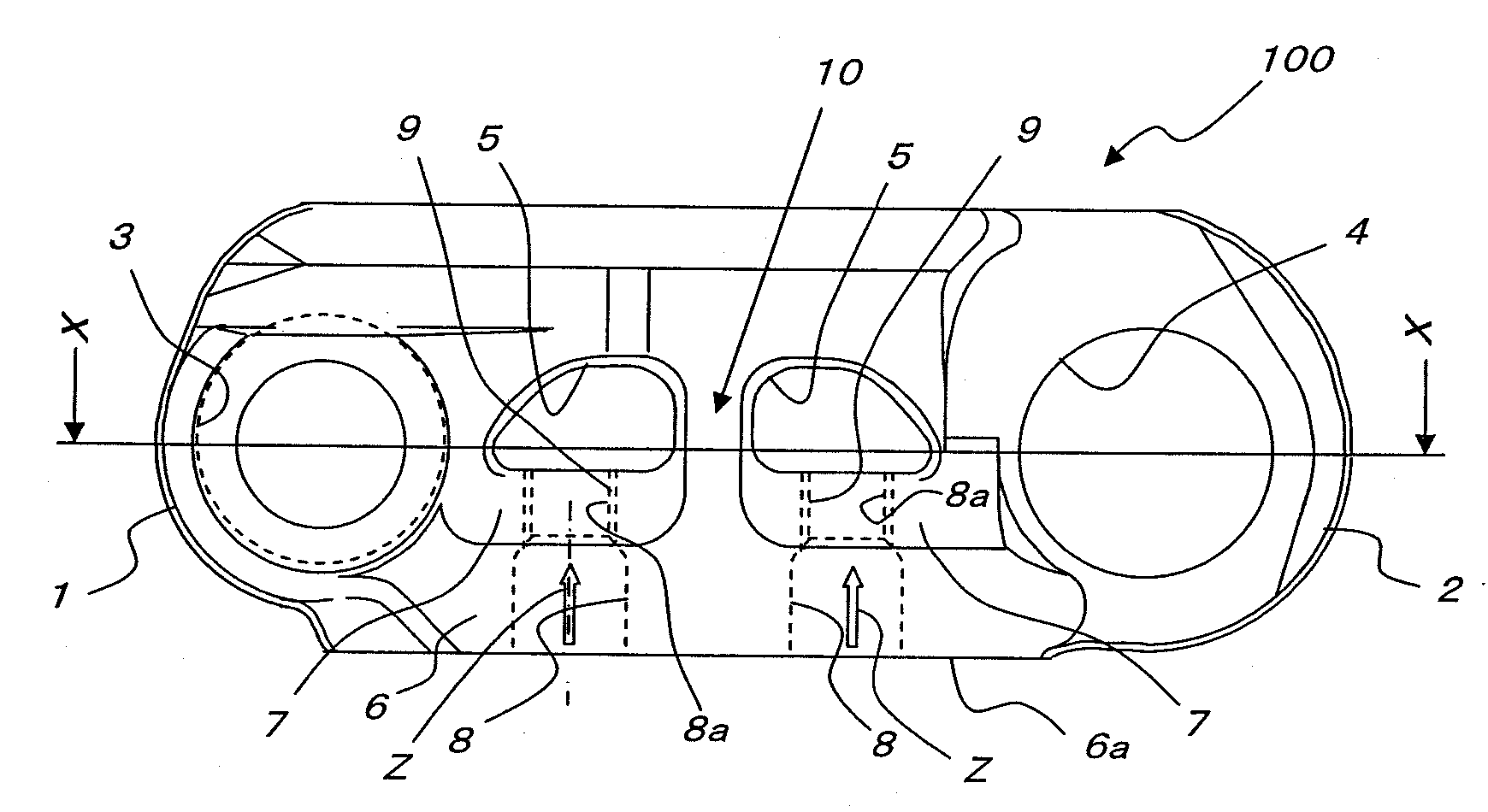
[0048]Firstly, the first embodiment is explained in reference to FIGS. 1 to 4.

[0049]In FIG. 1, in an endless track link a whole body of which is represented by the reference numeral 100, a first through-hole 3 is formed at the left end 1 and a second through-hole 4 is formed at the right end 2. Each of the first and second through-holes 3 and 4 is configured so that a pin and a bushing, which are not shown in the drawings, can be penetrated through such the through-hole.

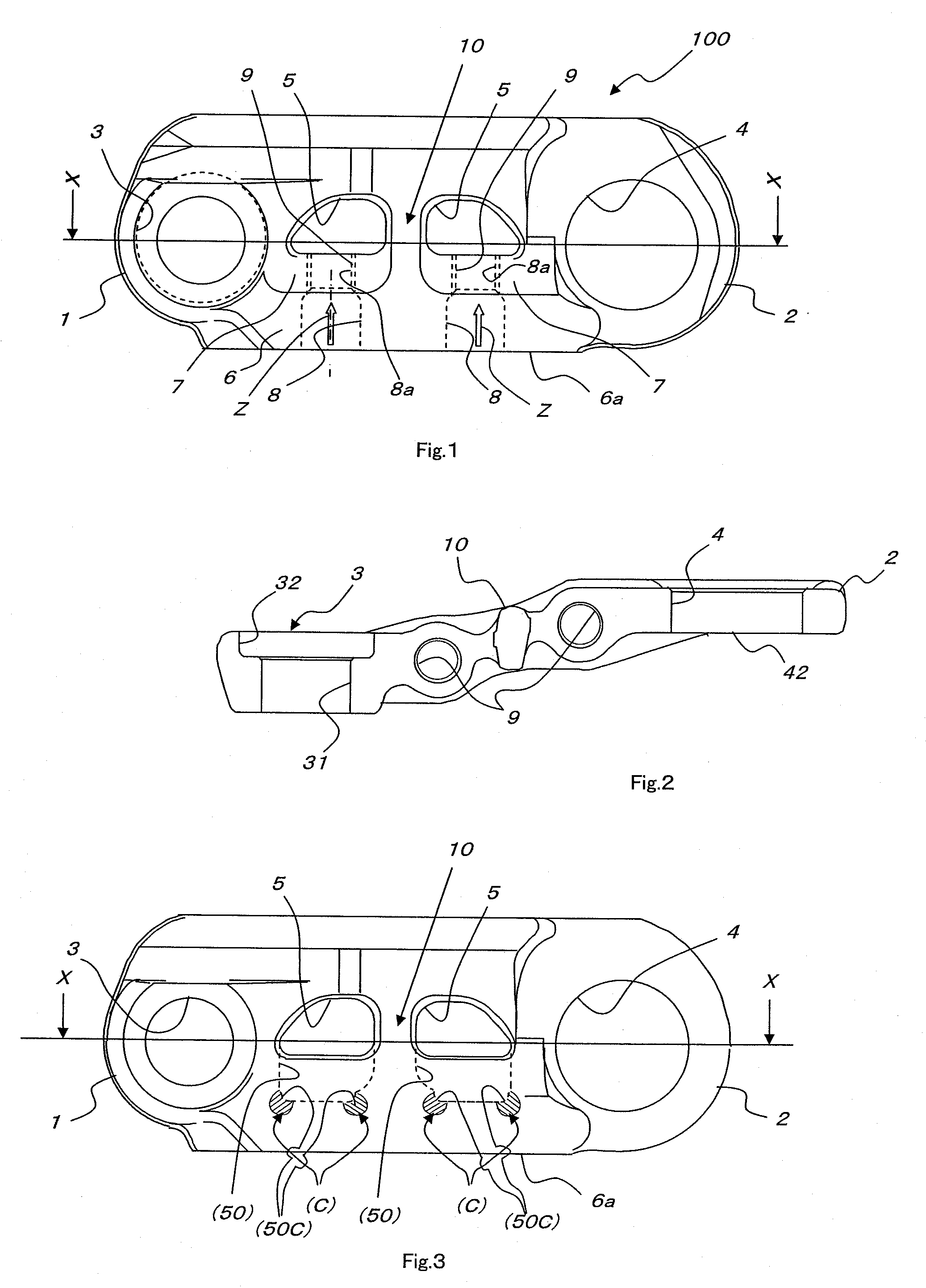
[0050]In FIG. 2, in the first through-hole 3, a counter bore 32 and a through-hole 31, which is concentric with the counter bore 32 and has a diameter being smaller than a diameter of the counter bore 32, are formed.

[0051]In the same way as explained in FIG. 9 showing the prior art, the opening 42 in the second through-hole 4 is constructed so as to face the counter bore 32 in the first through-hole 3 of an another link (not shown) at a generally flat plane, in a case that adjacent pieces are connected to each other....

second embodiment

[0082]Next, the second embodiment is explained in reference to FIG. 5.

[0083]In the first embodiment shown in FIGS. 1 to 4, two window areas 5, 5 are formed at two locations in the center of the link and the strut (a center pillar) 10 is formed between the window areas 5, 5.

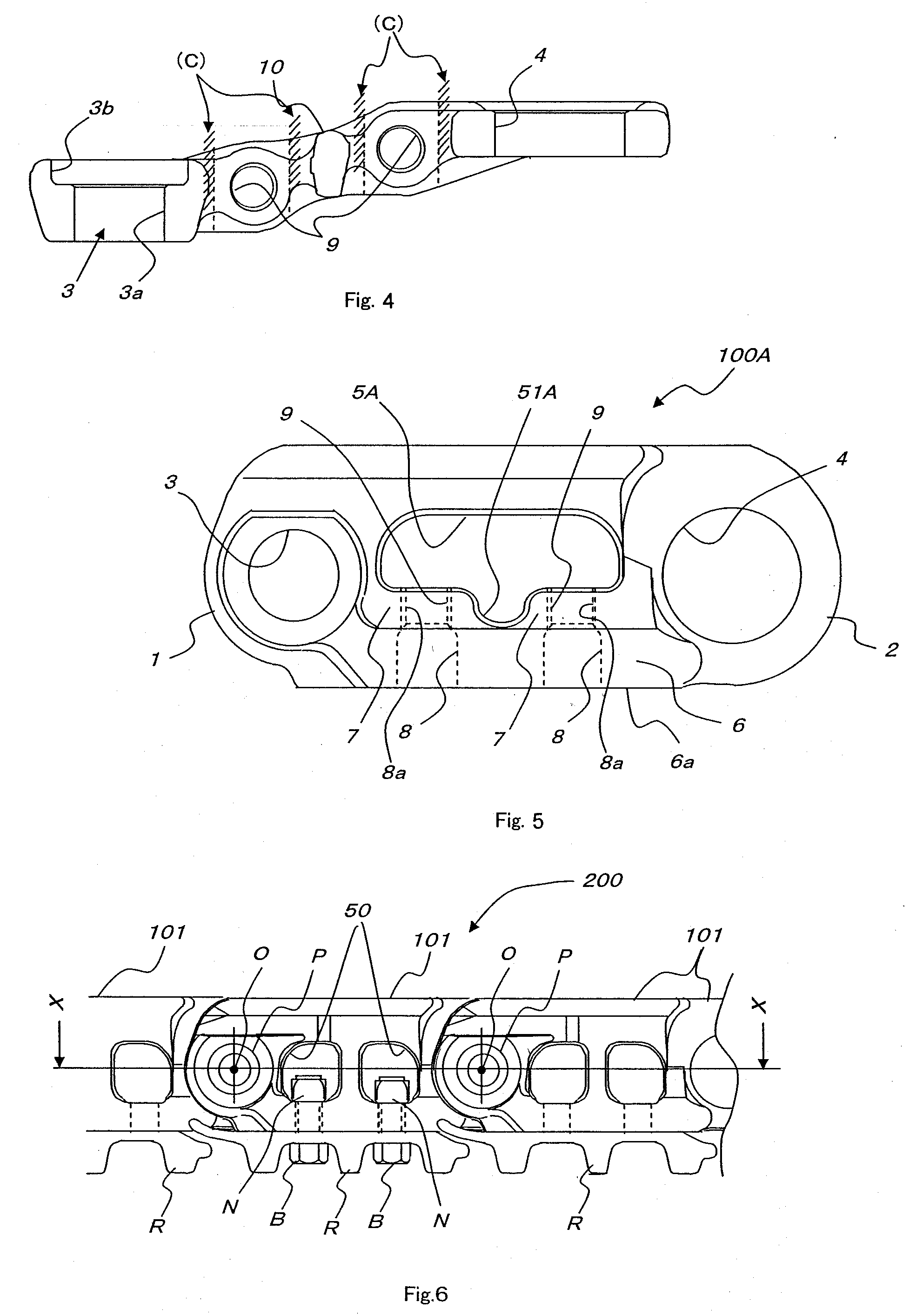
[0084]In contrast, in an endless track link 100A according to the second embodiment shown in FIG. 5, a single window area 5A is formed in place of the two window areas 5, 5 in the link 100 according to the first embodiment shown in FIG. 1, and the strut (the center pillar) 10 does not exist in the link 100A. A recess 51A is formed in the center of the lower periphery of the single window area 5A.

[0085]The endless track link 100A according to the second embodiment shown in FIG. 5, which does not have the strut (the center pillar) 10, which has the single window area 5A, and which has the recess 51A in the center of the lower periphery of the window area 5A, is used for a small excavator or a bulldozer.

[0086]The con...


PUM

PropertyMeasurementUnit
Tensile strengthaaaaaaaaaa

Abstract

An object of the present invention is to provide an endless track link being able to reduce stress concentrations and to improve efficiency of an assembling process of the endless track link.
The present invention is characterized in that: a reinforcing part (7) is formed in the region in which concentrates are generated in a window area (5); the reinforcing part (7) extends in a direction apart from a track shoe and includes an extended part of a through-hole (a plain through-hole 8 having a smooth inner surface) into which a track shoe connecting bolt is inserted; and a female thread (9) for engaging with the track shoe connecting bolt is formed at the extended part of the through-hole (8).

Description

TECHNICAL FIELD[0001]The present invention relates to an improvement of an endless track link which is a part of an endless track as a base carrier of a construction vehicle.PRIOR ART[0002]FIG. 6 is a side view showing a part of an endless track (a crawler belt) in a prior art and FIG. 7 is a sectional view taken on line X-X of FIG. 6.[0003]In FIGS. 6 and 7, an endless track a whole body of which is represented by the reference numeral 200 comprises a plurality of “pieces” (a unit of the endless track). Each piece comprises a track shoe R, a pair of links 101, 101 connected to the track shoe R, and a pin P connecting the piece to an adjacent piece (that fits into a bushing Bu in FIGS. 6 and 7).[0004]In FIGS. 6 and 7, a reference character B represents a bolt fastening a track shoe R to the endless track links 101, 101 a reference character N represents a nut being engaged with the bolt, and a reference character O represents a center axis of the pin P.[0005]In a link 101 shown in FI...

Claims


Application Information

Patent Timeline
IPC IPC(8): B62D55/20
CPCB62D55/28B62D55/21
Inventor SAKAI, TAKAOUEDA, MAKOTOKURIHARA, AKIYOSHINAKAGAWA, EIJIKINPARA, YUSUKE
Owner TOPY INDUSTRIES
Why Eureka
Try Eureka