Metal bonded drilling and boring tool

a drilling and boring tool technology, applied in the direction of turning machines, turning machine accessories, gear-teeth manufacturing apparatus, etc., can solve the problems of reducing the life of the cemented carbide bar, affecting the performance of the tool shaft, and affecting the service life of the tool sha

Inactive Publication Date: 2005-02-08
TENRYU SAW MFG
View PDF22 Cites 10 Cited by
  • Summary
  • Abstract
  • Description
  • Claims
  • Application Information

AI Technical Summary

Benefits of technology

It is therefore an object of the present invention to provide a metal bonded drilling and boring tool which can perform drilling and boring to a hard material such as a stone, concrete, and tile without the need for tool exchange.
Preferably, the connecting portion has a concave surface continuing to the outer circumferential surface of the rod-shaped body or has a frustoconical shape. Thus, the rod-shaped body and the enlarged mounting portion are connected by the connecting portion having a concave surface or a frustoconical shape, so that stress concentration occurring at the joint between the rod-shaped body and the connecting portion during boring can be suppressed. As a result, the life of the tool can be extended.
Preferably, the connecting portion has a concave surface or a frustoconical shape. With this structure, stress concentration at the joint between the rod-shaped body and the connecting portion during boring can be suppressed to thereby extend the life of the tool.

Problems solved by technology

Although a ceramics board containing a cement material may be bored by using a cemented carbide bar, the life of the cemented carbide bar is very short in this case.
Further, although a stone or tile may be bored by using a shafted abrasive wheel or diamond electrodeposited bar, such a tool has a characteristic of undergoing a large cutting resistance, causing a reduction in life.
Further, such a large cutting resistance causes exertion of a large force on the shaft of such a tool.
As a result, the tool may be broken before deterioration in cutting performance.

Method used


Image

  • Metal bonded drilling and boring tool
  • Metal bonded drilling and boring tool
  • Metal bonded drilling and boring tool

Examples


Embodiment Construction

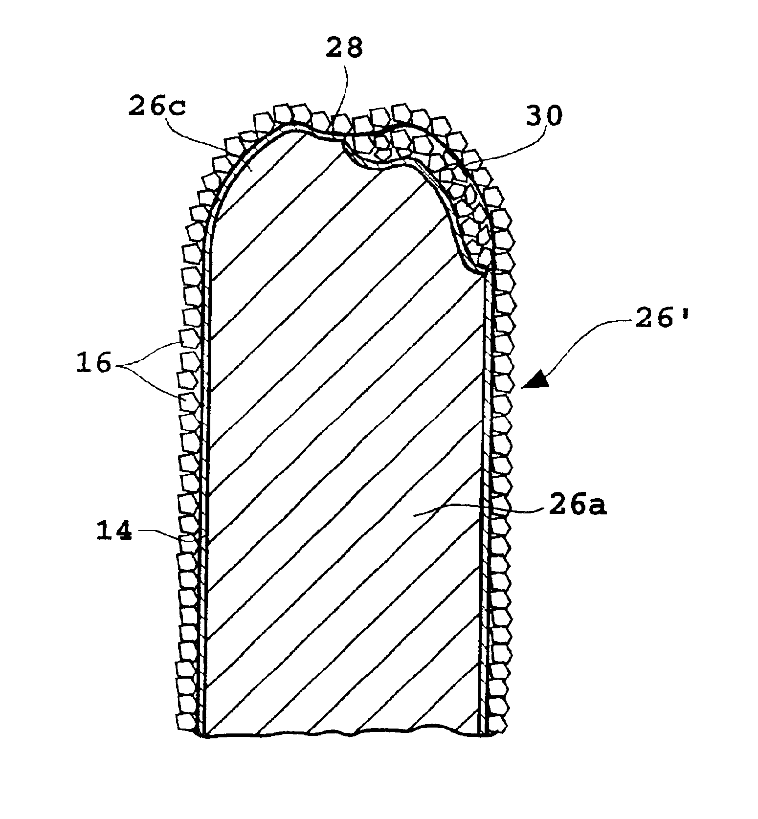
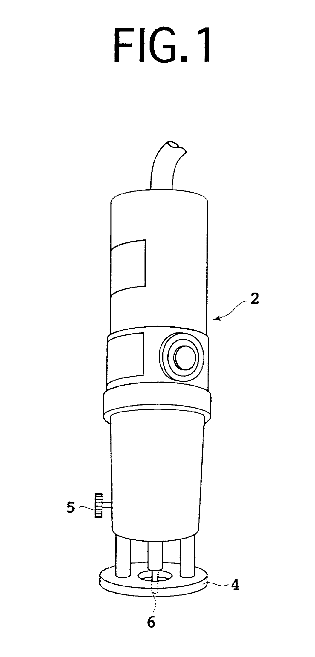
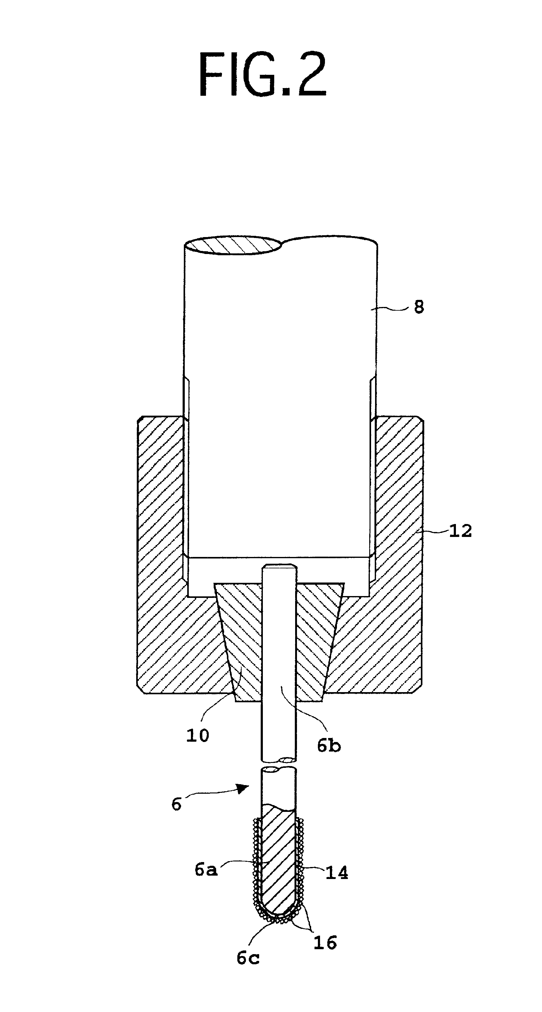
Some preferred embodiments of the present invention will now be described with reference to the drawings. In the following description of the preferred embodiments, substantially the same parts are denoted by the same reference numerals. Referring to FIG. 1, there is shown a perspective view of a hand grinder 2 to which the metal bonded drilling and boring tool of the present invention is mountable. A metal bonded drilling and boring tool 6 according to a first preferred embodiment of the present invention is detachably mounted on the hand grinder 2 at its front end (lower end). An annular member 4 for restricting the depth of cut by the tool 6 is adjustably mounted at the front end of the hand grinder 2. The annular member 4 can be adjusted in position by loosening a screw 5 to move the annular member 4 relative to the body of the hand grinder 2 and next tightening the screw 5 again.

FIG. 2 is a vertical sectional view of a tool mounting portion of the hand grinder 2. The hand grind...


PUM

PropertyMeasurementUnit
rockwell hardness HRCaaaaaaaaaa
diameteraaaaaaaaaa
lengthaaaaaaaaaa

Abstract

A metal bonded drilling and boring tool which can prevent the separation of abrasive grains during drilling and boring to maintain a stable working performance for a long period of time without the need for tool exchange. The tool includes a rod-shaped body having a substantially semispherical front end portion and numerous abrasive grains bonded to an outer circumferential surface of the rod-shaped body at the front end portion and at a portion having a given length from the front end portion by a bond member formed primarily of copper alloy. The bond member contains a material selected from the group consisting of Ti, Al, and a mixture thereof. The copper alloy is selected from the group consisting of bronze containing 10 to 33 wt % of Sn, brass containing 5 to 20 wt % of Zn, and aluminum bronze containing 5 to 20 wt % of Al.

Description

BACKGROUND OF THE INVENTION1. Field of the InventionThe present invention relates to a metal bonded drilling and boring tool.2. Description of the Related ArtIn the case of drilling a hole in a hard material such as a stone, concrete, and tile, it is conventionally general to mount a diamond core bit on an electric drill. Further, in the case of boring the drilled hole to enlarge its diameter, a so-called cemented carbide bar formed of cemented carbide alloy or high-speed steel is mounted on a trimmer, router, or hand grinder. In this mounted condition, the cemented carbide bar is rotated at a high speed of 10,000 rpm or more. As another conventional boring method, a shafted abrasive wheel or an electrodeposited bar formed by electrodeposition of diamond abrasive grains on a steel bar is mounted on a trimmer, router, or hand grinder. In this mounted condition, the shafted abrasive wheel or the diamond electrodeposited bar is rotated at a high speed.Thus, the boring is performed by u...

Claims


Application Information

Patent Timeline
Patent Type & Authority Patents(United States)
IPC IPC(8): B23C5/10B24D3/00B24D3/02B24D3/06B24D7/00B24D7/18B28D1/14
CPCB23C5/1009B24D7/18B23C2222/04B23C2222/88B23C2228/10Y10T408/81Y10T82/2511Y10T82/2522Y10T408/78
Inventor TAKEMURA, SOKICHIKUSACHI, YOSHIKAZUNAKAGAWA, AKIHIKO
Owner TENRYU SAW MFG
Why Eureka
Try Eureka