Manufacturing method for helical core for rotating electrical machine and manufacturing device for helical core for rotating electrical machine

a technology of rotating electrical machines and manufacturing devices, which is applied in the direction of manufacturing stator/rotor bodies, magnetic circuit shapes/forms/construction, manufacturing tools, etc., can solve the problems of increasing material costs, reducing the yield of helical cores, and increasing the thickness of outer circumferential sides of belt-shaped metal plates (yokes). , to achieve the effect of improving yield, improving characteristics, and reducing the cost of helical cores

Active Publication Date: 2013-10-24
NIPPON STEEL CORP
View PDF15 Cites 10 Cited by
  • Summary
  • Abstract
  • Description
  • Claims
  • Application Information

AI Technical Summary

Benefits of technology

[0028]According to the present invention, the notch portion, in addition to the yoke portion and the tooth portion, is formed on the belt-shaped steel sheet (belt-shaped metal plate) that forms the helical core for a rotating electrical machine. The notch portion is formed at the position between tooth portions of the yoke portion. By forming the notch portion on the belt-shaped steel sheet, when the helical core for a rotating electrical machine is formed, it is possible to prevent the thickness of the outer circumferential side of the yoke of helical core for a rotating electrical machine from being thinner than the thickness of the inner circumferential side. Moreover, when the belt-shaped steel sheet is processed into a helical shape, stress can be more concentrated in the outer circumferential side region of the yoke portion than in the notch portion. Accordingly, unlike the related art, it is not necessary to perform a specific treatment after processing the belt-shaped steel sheet into a helical shape, or to process the shape of the belt-shaped steel sheet processed into a helical shape in a complicated shape. Furthermore, a helical core for a rotating electrical machine having improved characteristics can be obtained, and costs of the helical core for a rotating electrical machine can be decreased.
[0029]When the helical core for a rotating electrical machine is manufactured, the yoke portion and the tooth portion, and the notch portion are separately formed on the belt-shaped steel sheet, and the belt-shaped steel sheet is processed into a helical shape at the position within the predetermined dimension after the notch portion is formed on the belt-shaped steel sheet. Thus, bending of the belt-shaped steel sheet after the notch is formed can be suppressed if possible, and the belt-shaped steel strip having various sheet numbers (from one sheet to the plurality of sheets) can be flexibly prepared from one belt-shaped steel sheet. Accordingly, magnetic characteristics, yield, and production flexibility of the helical core for a rotating electrical machine are increased, and costs of the helical core for a rotating electrical machine can be further decreased.

Problems solved by technology

Therefore, the yield of the metal plate is decreased, and the material costs are increased.
However, if the bending process in the plate surface is performed on the belt-shaped metal plate, the outer circumferential side of the portion corresponding to the yoke of the belt-shaped metal plate extends more largely than the inner circumferential side, and there is a concern that the thickness of the outer circumferential side of the belt-shaped metal plate (yoke) may be thinner than the thickness of the inner circumferential side.

Method used


Image

  • Manufacturing method for helical core for rotating electrical machine and manufacturing device for helical core for rotating electrical machine
  • Manufacturing method for helical core for rotating electrical machine and manufacturing device for helical core for rotating electrical machine
  • Manufacturing method for helical core for rotating electrical machine and manufacturing device for helical core for rotating electrical machine

Examples


example 1

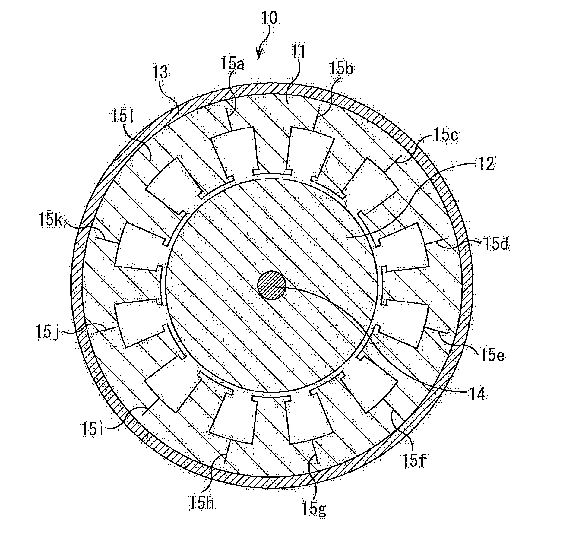
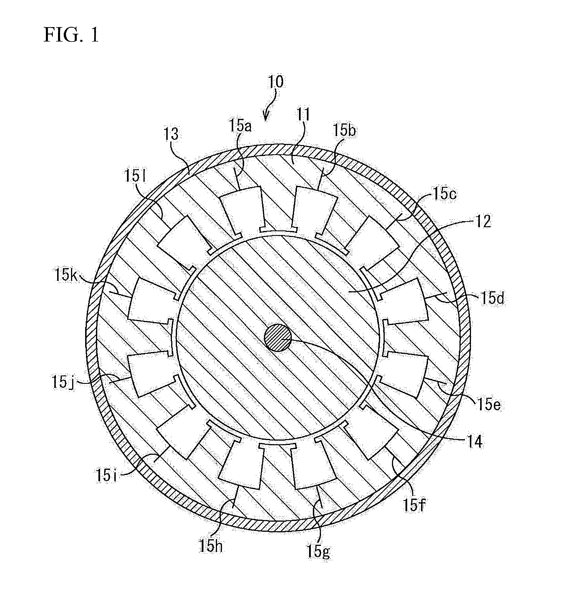
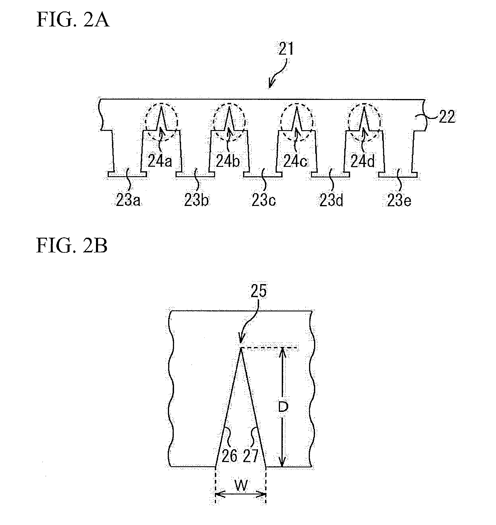
[0095]The belt-shaped steel sheet having the shape shown in FIG. 2A was prepared using a product hoop of SPCC-SD (0.02% C) defined by JIS G3141 and 0.50 mm thickness and a magnetic steel sheet product hoop of 0.002% C, 0.1% Si, and 0.35 mm thickness, and a helical core stator of 30 mm thickness was manufactured. In the helical core stator, the outer diameter of the stator was 120 mmφ, and the inner diameter (the inner diameter that includes the bottom of the slot) of the tooth root portion was 90 mmφ. Moreover, the depth dimensions of the cut line 15 shown in FIG. 1 were variously changed with respect to the length (width dimension) in the width direction of the yoke (hereinafter, the depth dimension of the cut line 15 with respect to the length in the width direction of the yoke is referred to as a ratio of the notch portion). Furthermore, an integral round-punched core was also prepared as Comparative Example. Evaluation results of the ratio of the notch portion and the shape of t...

example 2

[0096]The belt-shaped steel sheet having the shape shown in FIG. 2A was prepared using a product hoop of 35A210 (3.1% Si) defined by JIS C2552 and 0.35 mm thickness, and a helical core stator of 30 mm thickness was manufactured. In the helical core stator, the outer diameter of the stator was 200 mmφ, and the inner diameter of the tooth root portion was 180 mmφ. Moreover, the depth dimensions of the cut line 15 shown in FIG. 1 were variously changed with respect to the length in the width direction of the yoke (hereinafter, the depth dimension of the cut line 15 with respect to the length in the width direction of the yoke is referred to as a ratio of the notch portion). Furthermore, an integral round-punched core was also prepared as Comparative Example. Evaluation results of the ratio of the notch portion and the shape of the steel sheet of the region 25 (stress concentrated portion) shown in FIG. 2B are shown in Table 3. The evaluation method was performed using the same criteria...

example 3

[0097]The belt-shaped steel sheet having the shape shown in FIG. 6A was prepared using a product hoop of 50A470 (2.0% Si) defined by JIS C2552 and 0.50 mm thickness and a product hoop of 50A800 (0.8% Si) defined by JIS C2552 and 0.50 mm thickness, and a helical core stator of 30 mm thickness was manufactured. In the helical core stator, the outer diameter of the stator was 120 mmφ, and the inner diameter of the tooth root portion was 90 mmφ. Moreover, the depth dimensions of the cut line 52 shown in FIG. 5 were variously changed with respect to the length in the width direction of the yoke (hereinafter, the depth dimension of the cut line 15 with respect to the length in the width direction of the yoke is referred to as a ratio of the notch portion). Furthermore, an integral round-punched core was also prepared as Comparative Example. Evaluation results of the ratio of the notch portion and the shape of the steel sheet of the stress concentrated portion near the circular portion of ...


PUM

PropertyMeasurementUnit
diameteraaaaaaaaaa
diameteraaaaaaaaaa
thicknessaaaaaaaaaa

Abstract

A manufacturing method of a helical core for a rotating electrical machine includes: first step forming a yoke portion extending along one direction and tooth portions protruding toward a width direction of the yoke portion from a first side edge of the width direction, with respect to a belt-shaped metal plate extending along the one direction; second step forming a notch at a position between tooth portions of the yoke portion after the first step; and third step processing the belt-shaped metal plate into a helical shape by applying bending to the metal plate so that the belt-shaped metal plate is curved toward the width direction sequentially from a portion where the notch is formed after the second step, and in the third step, a distance between a position where the application of bending starts and the position where the notch is formed is limited to within a predetermined dimension.

Description

TECHNICAL FIELD[0001]The present invention relates to a manufacturing method of a helical core for a rotating electrical machine. Particularly, the present invention is suitably used in the manufacturing of a helically coiled core (helical core) that is used in a rotating electrical machine.BACKGROUND ART[0002]A core of a stator (referred to as a stator core as necessary in descriptions below) of a rotating electrical machine of a generator, an electric motor, or the like is formed by laminating metal plates such as a magnetic steel sheet. The stator core includes a yoke that extends in a circumferential direction of the stator core, and a plurality of teeth that extend in a direction of a rotating shaft from an inner circumferential surface of the yoke. In order to manufacture the stator core, a core piece, which has the same shape as the shape (shape on the plate surface) when viewed from thickness directions of the yoke and the teeth, is punched from a metal plate, and the core p...

Claims


Application Information

Patent Timeline
Patent Type & Authority Applications(United States)
IPC IPC(8): H02K15/02
CPCH02K15/02H02K1/148H02K15/022H02K15/026Y10T29/49009Y10T29/53691H02K1/18
Inventor KUROSAKI, YOUSUKE
Owner NIPPON STEEL CORP
Why Eureka
Try Eureka