Gas barrier film laminate, member for electronic device, and electronic device

Inactive Publication Date: 2015-03-05
LINTEC CORP
View PDF10 Cites 11 Cited by
  • Summary
  • Abstract
  • Description
  • Claims
  • Application Information

AI Technical Summary

Benefits of technology

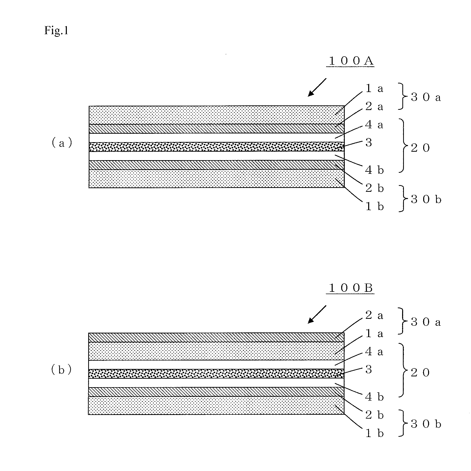
[0015]Since the gas barrier film laminate according to one aspect of the invention includes the bonding layer having the above properties, concentration of bending stress is reduced at the interface between the gas barrier film (having a larger thickness) and the bonding layer when the gas barrier film laminate is bent, and it is possible to solve a problem in which delamination (separation) and lifting occur at the interface between the gas barrier film (having a larger thickness) and the pressure-sensitive adhesive layer.
[0016]The gas barrier film laminate according to

Problems solved by technology

However, a plastic film easily allows water vapor, oxygen, and the like to pass through as compared w

Method used


Image

  • Gas barrier film laminate, member for electronic device, and electronic device
  • Gas barrier film laminate, member for electronic device, and electronic device
  • Gas barrier film laminate, member for electronic device, and electronic device

Examples


Example

Example 1

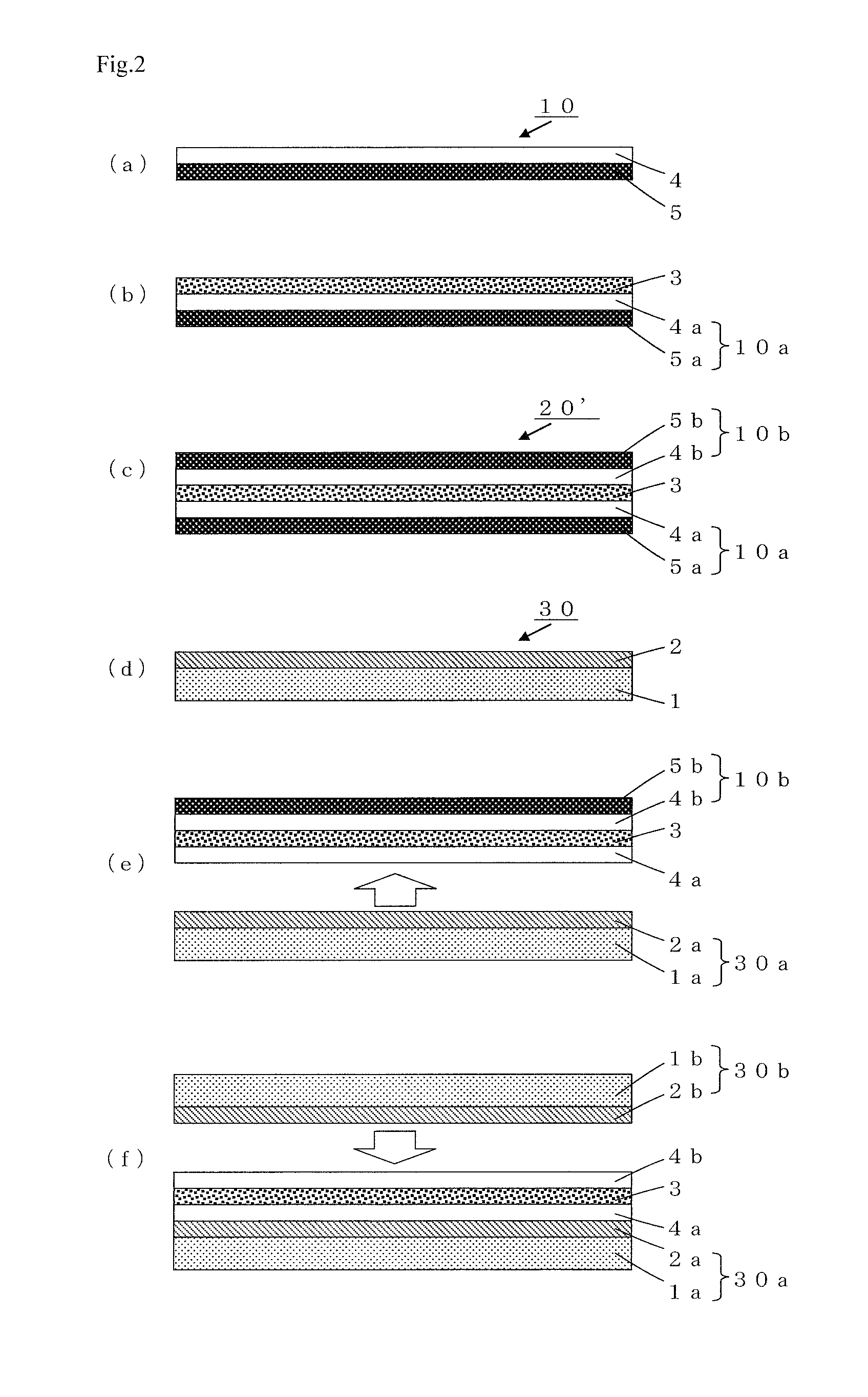
[0226]The pressure-sensitive adhesive composition A was applied to the surface of a release layer of a release film in which a silicone release layer was provided on one side of a PET film having a thickness of 38 μm (“SP-PET381031” manufactured by Lintec Corporation) using a comma direct coating method, and the resulting film was dried at 100° C. for 1 minute to obtain a release film A provided with a pressure-sensitive adhesive layer having a thickness of 2 μm.

[0227]The pressure-sensitive adhesive layer of one release film A was bonded to the resin film 1, and the pressure-sensitive adhesive layer of another release film A was bonded to the resin film 1 to obtain a laminate A for forming a bonding layer.

[0228]After removing one of the release films from the laminate A, the exposed pressure-sensitive adhesive layer was bonded to the gas barrier layer of the gas barrier film A. After removing the other release film from the laminate A, the exposed pressure-sensitive adhesiv...

Example

Example 2

[0229]A gas barrier film laminate B was produced in the same manner as in Example 1, except that the resin film 2 was used as the base film of the bonding layer instead of the resin film 1.

Example

Comparative Example 1

[0230]The pressure-sensitive adhesive composition A was applied to the surface of a release layer of the above release film (“SP-PET381031” manufactured by Lintec Corporation) using a comma direct coating method, and the resulting film was dried at 100° C. for 1 minute to obtain a release film B provided with a pressure-sensitive adhesive layer having a thickness of 6 μm.

[0231]The gas barrier layer of the gas barrier film A was bonded to the pressure-sensitive adhesive layer of the release film B, and the release film was removed.

[0232]The exposed pressure-sensitive adhesive layer was bonded to the gas barrier layer of the gas barrier film B to produce a gas barrier film laminate C that did not include the base film A.


PUM

PropertyMeasurementUnit
Temperatureaaaaaaaaaa
Thicknessaaaaaaaaaa
Thicknessaaaaaaaaaa

Abstract

The present invention is a gas barrier film laminate comprising at least two gas barrier films and a bonding layer, the at least two gas barrier films being stacked through the bonding layer, the bonding layer having a configuration in which a pressure-sensitive adhesive layer is contiguously stacked on each side of a base film A, the base film A being formed of a synthetic resin having a tensile modulus at 23° C. of 3000 to 10,000 MPa. The present invention is also an electronic device member comprising the gas barrier film laminate. According to the present invention, provided are a gas barrier film laminate that exhibits an excellent gas barrier capability and excellent bendability, an electronic device member that includes the gas barrier film laminate, and an electronic device that includes the electronic device member.

Description

TECHNICAL FIELD[0001]The invention relates to a gas barrier film laminate that exhibits an excellent gas barrier capability and excellent bendability, an electronic device member that includes the gas barrier film laminate, and an electronic device that includes the electronic device member.BACKGROUND ART[0002]Use of a transparent plastic film as a substrate for an electronic member (e.g., solar cell, liquid crystal display, or electroluminescence (EL) display) instead of a glass sheet (plate) has been studied in order to implement a reduced thickness, a reduced weight, flexibility, impact resistance, and the like. However, a plastic film easily allows water vapor, oxygen, and the like to pass through as compared with a glass sheet, and may easily cause a deterioration in elements provided in the electronic member.[0003]In order to solve the above problem, Patent Document 1 discloses a flexible display substrate in which a transparent gas barrier layer formed of a metal oxide is sta...

Claims


Application Information

Patent Timeline
IPC IPC(8): B32B7/12B32B27/08B32B7/02B32B27/28
CPCB32B7/12B32B2307/7246B32B27/08B32B7/02B32B2250/05B32B2250/40B32B2307/54B32B2398/00B32B2457/208B32B2457/206B32B2457/20B32B2457/12B32B2457/202B32B2307/7244B32B27/28B32B2307/7242G02F1/133305G02F2201/501H01L31/049Y02E10/50Y10T428/2495Y10T428/264Y10T428/265Y10T428/266H10K30/88H10K77/111H10K50/8445H10K50/84
Inventor IWAYA, WATARUNAGANAWA, SATOSHI
Owner LINTEC CORP
Why Eureka
Try Eureka