Electronic lock for safes

a safe and electronic technology, applied in safes, non-mechanical controls, instruments, etc., can solve the problems of loss of affirmative lock feedback, limited ability to automatically manage false latching conditions, and inability to effectively lock the safe door in place, so as to reduce the requirements of tight mechanical tolerance

Active Publication Date: 2018-03-08
ELLENBY TECH
View PDF11 Cites 9 Cited by
  • Summary
  • Abstract
  • Description
  • Claims
  • Application Information

AI Technical Summary

Benefits of technology

[0008]One aspect of the present invention is the recognition that electronic sensing of a bolt using a non-contact se

Problems solved by technology

Gartner further addresses another drawback of many electronic safe locks in that they lack assurance that they have effectively locked the safe door in place.
In Gartner's described configuration, both the cross bolt and the switch plunger may be subjected to physical wear over time resulting in a loss of affirmative lock feedback.
Additionally, in Gartner's arrangement, the system has limited ability to automatically manage false latching conditions as the user is required to manually insert a key to force the solenoid to re-energize to once again retract the cross bolt.
Typically, these types of tolerances are difficult to control and result in requiring generous over-travel of the bolt or sizeable actuat

Method used


Image

  • Electronic lock for safes
  • Electronic lock for safes
  • Electronic lock for safes

Examples


Embodiment Construction

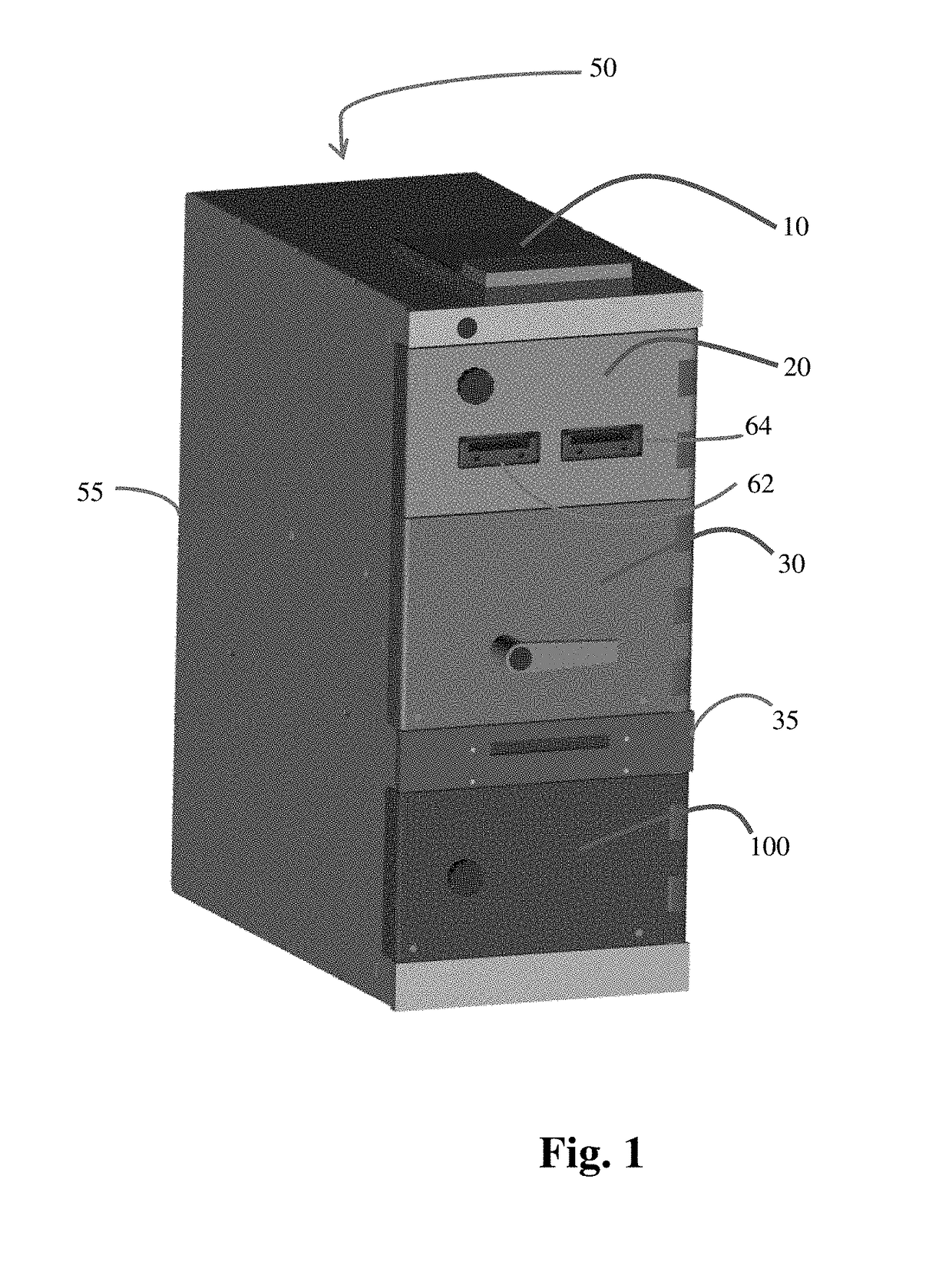
[0036]Referring to FIG. 1, an electronic safe 50 is shown including a safe housing 55, safe top door 20, safe center door 30 and safe bottom door 100. The electronic safe 50 also has a user keypad and display module or interface 10 for users to enter their identification and other information as well as receive messages from the safe system. Further details of electronic safes and coin and bill dispensing safes with which the present invention may be advantageously employed are found in U.S. Patent Application Publication Nos. 2002 / 0063034; 2004 / 0046018; 2011 / 0279225; 2011 / 0011927; and U.S. Pat. Nos. 7,516,832; 7,779,983; and 8,770,372, all of which are assigned to the assignee of the present invention and incorporated by reference herein in their entirety.

[0037]In one embodiment, the electronic safe 50 houses electronic bill acceptors, 62 and 64, to allow bills to be deposited into the safe. The electronic safe will record the identity of the person depositing the bills as well as ...


PUM


Abstract

An electronic lock with an electronic sensing arrangement to accurately sense relative positions of a bolt which mechanically locks a door, such as a door of an electronic drop safe, and to also sense an electronically controlled plunger which locks the bolt in place. The arrangement provides a mechanism for sensing a variety of mechanical malfunctions, as well as, potential fraud or tampering situations.

Description

CROSS REFERENCE TO RELATED APPLICATION[0001]The present application claims the benefit of U.S. Provisional Patent Application Ser. No. 62 / 383,936 filed Sep. 6, 2016 entitled “Electronic Lock for Safes” which is incorporated by reference herein in its entirety.FIELD OF THE INVENTION[0002]The present invention relates generally to improved electronic locks, and more particularly to electronic locks and sensing techniques to confirm their proper operation adapted to electronic drop safes and the like.BACKGROUND OF THE INVENTION[0003]Electronic locks are a popular feature of modern safes and strong boxes for several reasons. First, they enable the use of advanced authentication methods including PIN codes, biometric sensors such as fingerprint, palm, or retina scanning, programmed time of day unlocking, or some combination of the above. Second, the use of an electronic lock facilitates the creation of electronic records of opening the lock. Third, unlock codes can be added or modified w...

Claims


Application Information

Patent Timeline
IPC IPC(8): E05B47/06E05B65/00E05G1/04G01D5/34
CPCE05B47/0603E05B65/0075E05G1/04E05B47/0012E05B2047/0069E05B2047/0016G01D5/342E05B2047/002E05B15/022E05B17/2038E05B17/2007E05B63/24
Inventor DOBBINS, AARON H.DOBBINS, BOB M.HENRY, JAMES
Owner ELLENBY TECH
Why Eureka
Try Eureka