Household appliance light

a technology for household appliances and light bulbs, which is applied in the field of household appliance light bulbs, can solve the problems of reducing the light yield and illumination quality of the interior of the house appliance, the typical contradictory and difficult to meet in their entirety, and the new challenges of engineers, so as to maximize the illumination of the interior space

Active Publication Date: 2018-03-08
BJB GMBH & CO KG
View PDF13 Cites 2 Cited by
  • Summary
  • Abstract
  • Description
  • Claims
  • Application Information

AI Technical Summary

Benefits of technology

[0014]Thus, it is an object of the invention to provide a compact household appliance light in particular for cooking appliances wherein a useable light output of the LED that is effective for interior space illumination is maximized.
[0016]The essential advantage of the household appliance light according to the invention is that two different light influencing light components are used for maximizing the light yield. The light conductor that is made from one material, for example a light conductor rod made from a synthetic material or glass, thus a light conductor made form a solid material receives the light of the LED, bundles it and conducts it with minimum scatter losses proximal to the light exit opening of the light housing, thus proximal to the inner wall of the household appliance space. Thus, the light conductor is arranged in the reflector space at least in sections so that the scatter radiation exiting from the light conductor is received and also directed towards the light outlet opening of the light housing, thus towards the interior of the household appliance. By the same token the light conductor facilitates a maximum offset of the LED from the household appliance interior and is used for heat shielding. A reflector is also used for heat shielding wherein the reflector does not only reflect the scatter light but also thermal radiation entering from the interior of the housing.
[0020]It is furthermore provided that the reflector directs the scatter light mostly in a direction towards the cone axis of the light cone exiting from the light exit surface of the light conductor so that also a blinding of the user caused by the reflective scatter light is mostly prevented.
[0025]The offset of the light conductor relative to the apex axis, in particular an offset away from the first reflection surface causes a stronger scatter light yield through the first reflection surface. Due to the inclination of the light exit surface recited supra the direct light exiting from the light exit surface as well as the scatter light reflected back by the reflector is run approximately in the same direction into the interior of the household appliance.

Problems solved by technology

No matter whether the household appliances are used for storing food products, for example cooling devices, or household appliances for cooking food products, for example ovens, there are particular requirements which are typically contradictory and hard to meet in their entirety.
By the same token this technology generates new challenges for engineers.
In the known art the described measures for offsetting the LED from the cooking cavity and for heat shielding reduce the light yield and the illumination quality of the interior of the household appliance.
In order to compensate for the reduced light yield more powerful LED's can be used, but their higher operating temperature causes problems,
Additionally the plurality of punctiform sources in the inner housing wall with their high level of brightness is perceived as unpleasant so that these solutions are not very popular due to being expensive and due to a lack of comfort.
Due to the standardized outer dimensions and the goal to keep the usable interior of the cooking device as large as possible the installation spaces provided between the lateral interior walls are rather limited.
This makes it difficult to design household appliance lights for cooking devices for using LED's since the distance between the cooking space and the LED that can be used for temperature protection is limited.
Thus, the light losses inherent to the known devices cannot easily be compensated by more powerful LED's in particular when the household appliance light is arranged behind a side wall of a cooking cavity since the more powerful LED's typically generate much more waste heat.

Method used


Image

  • Household appliance light
  • Household appliance light
  • Household appliance light

Examples


Embodiment Construction

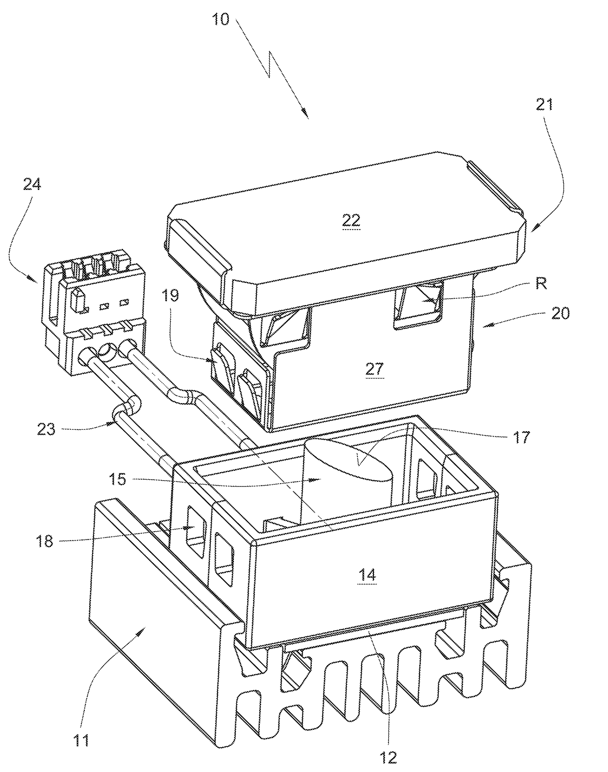
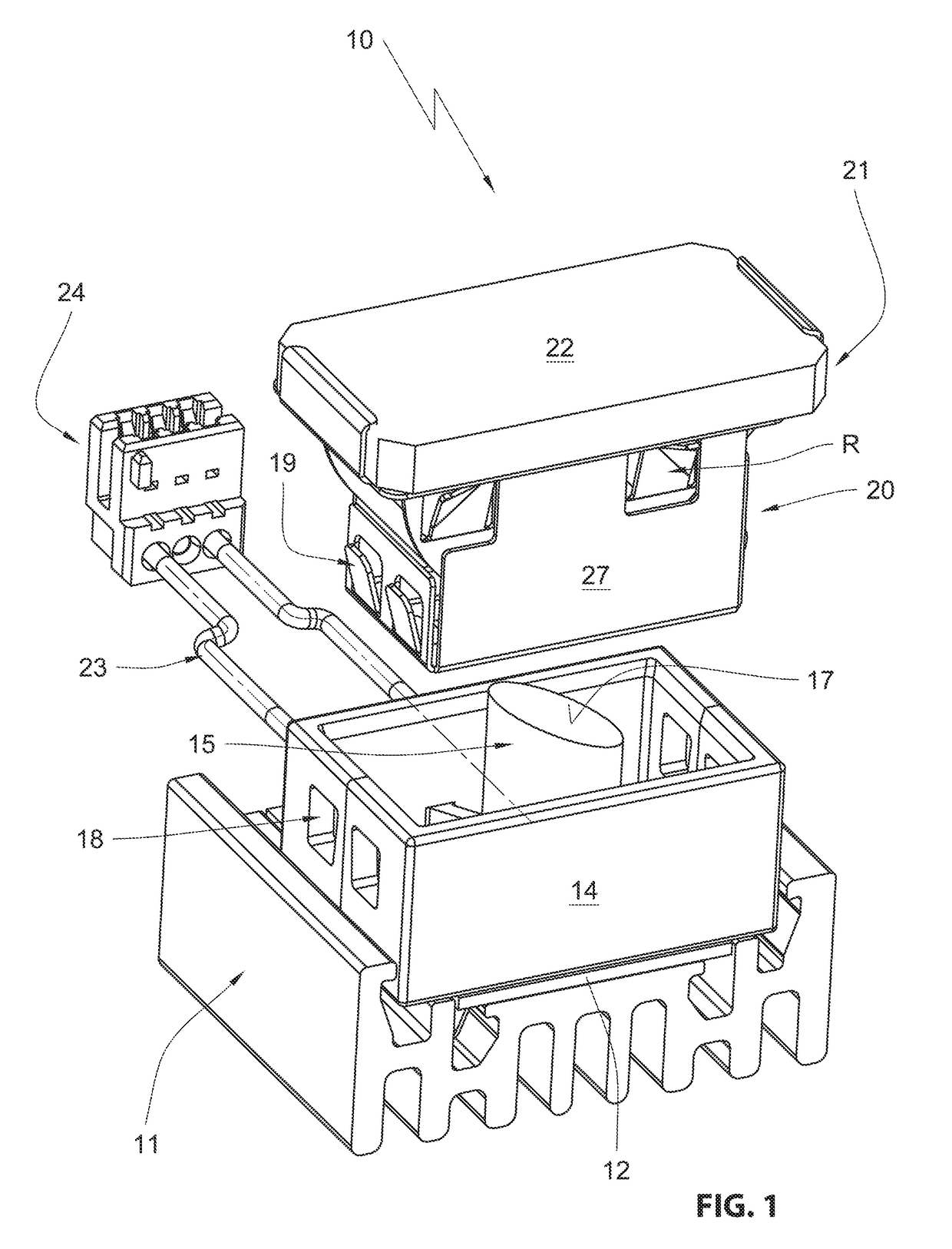
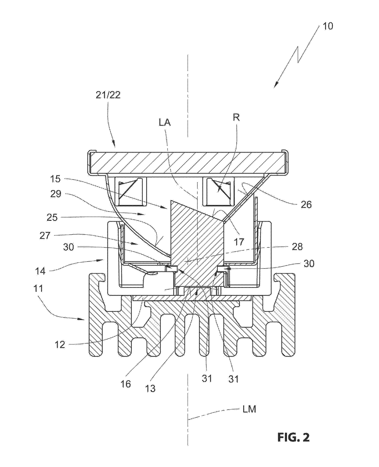
[0038]In the drawing figures a household appliance light simply referred as a light is designated overall with the reference numeral 10. The household appliance light according to FIG. 1 includes a cooling element 11 on which a circuit board 12 is arranged with an applied LED 13 (FIG. 2)

[0039]Additionally a light housing 14 made from an electrically and thermally insulating material like e.g. plastic or ceramic is arranged on the cooling element wherein a light conductor 15 is arranged in the light housing. In the instant embodiment this is a rod shaped light conductor made from glass. The light conductor includes a light entry surface 16 that is arranged proximal to the LED (FIG. 2) and a light exit surface 17 that is arranged remote from the LED. The light exit surface 17 is inclined relative to a center axis of the light conductor 15. With respect to the circuit board 12 the center axis is sloped downward towards the circuit board 12. Furthermore the light exit surface is configu...


PUM


Abstract

A household appliance light, in particular a light for cooking devices like ovens, microwaves or steam cookers, the household appliance light including a LED configured as an illuminant; a light housing configured to be arranged at a wall of the household appliance; a light exit opening arranged in the light housing which is enclosed by a light permeable cover; a spacer element which is arranged between the LED and the light exit opening and which is arranged in front of a light outlet plane of the LED; and a reflection device which conducts light emitted by the LED to the cover, wherein the spacer element is a light conductor that is made from one uniform material, wherein the reflection device is a reflector which defines a reflector cavity, and wherein the light conductor is run into the reflector cavity.

Description

RELATED APPLICATIONS[0001]This application claims priority from and incorporates by reference German Patent ApplicationsDE 20 2016 104 855.9 filed on Sep. 2, 2016, andDE 10 2016 118 041.6 filed on Sep. 23, 2016,both are which are incorporated in their entirety by this reference.FIELD OF THE INVENTION[0002]The invention relates to a household appliance light, in particular a light for cooking devices like ovens, microwaves or steam cookers, including a LED for an illuminant, a light housing configured to be arranged at a wall of the household appliance, a light exit opening arranged in the light housing which light exit opening is closed by a light permeable cover, a spacer element which is arranged between the LED and the light exit opening and which is arranged in front of the light exit plane of the LED, a reflection device which conducts the light emitted by the LED to the cover.BACKGROUND OF THE INVENTION[0003]Household appliance lights are well known in the art in many embodime...

Claims


Application Information

Patent Timeline
Patent Type & Authority Applications(United States)
IPC IPC(8): F24C15/00F24C7/08
CPCF24C7/082F24C15/008H05B6/6444F21K9/233F21K9/61F21V13/02F21V33/0044F21W2131/307
Inventor BAUMEISTER, OLAFHERBST, THOMAS
Owner BJB GMBH & CO KG
Why Eureka
Try Eureka