Light-emitting device

Active Publication Date: 2018-03-08
PIONEER CORP +1
View PDF3 Cites 1 Cited by
  • Summary
  • Abstract
  • Description
  • Claims
  • Application Information

AI Technical Summary

Benefits of technology

[0007]In order to provide a light-emitting device using an organic EL with optical transparency, a region transmitting light from the outside may be provided in the light-emitting device, as described in Patent Doc

Problems solved by technology

However, since no light-emitting unit is formed in this region, a percentage of the region where th

Method used


Image

  • Light-emitting device
  • Light-emitting device
  • Light-emitting device

Examples


Example

Modification Example 1

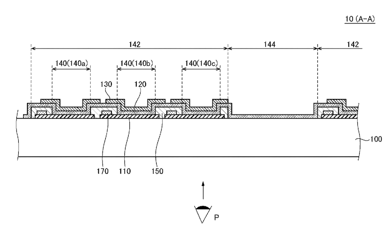
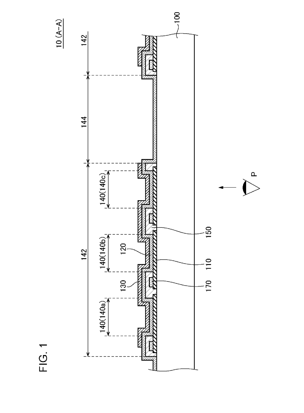
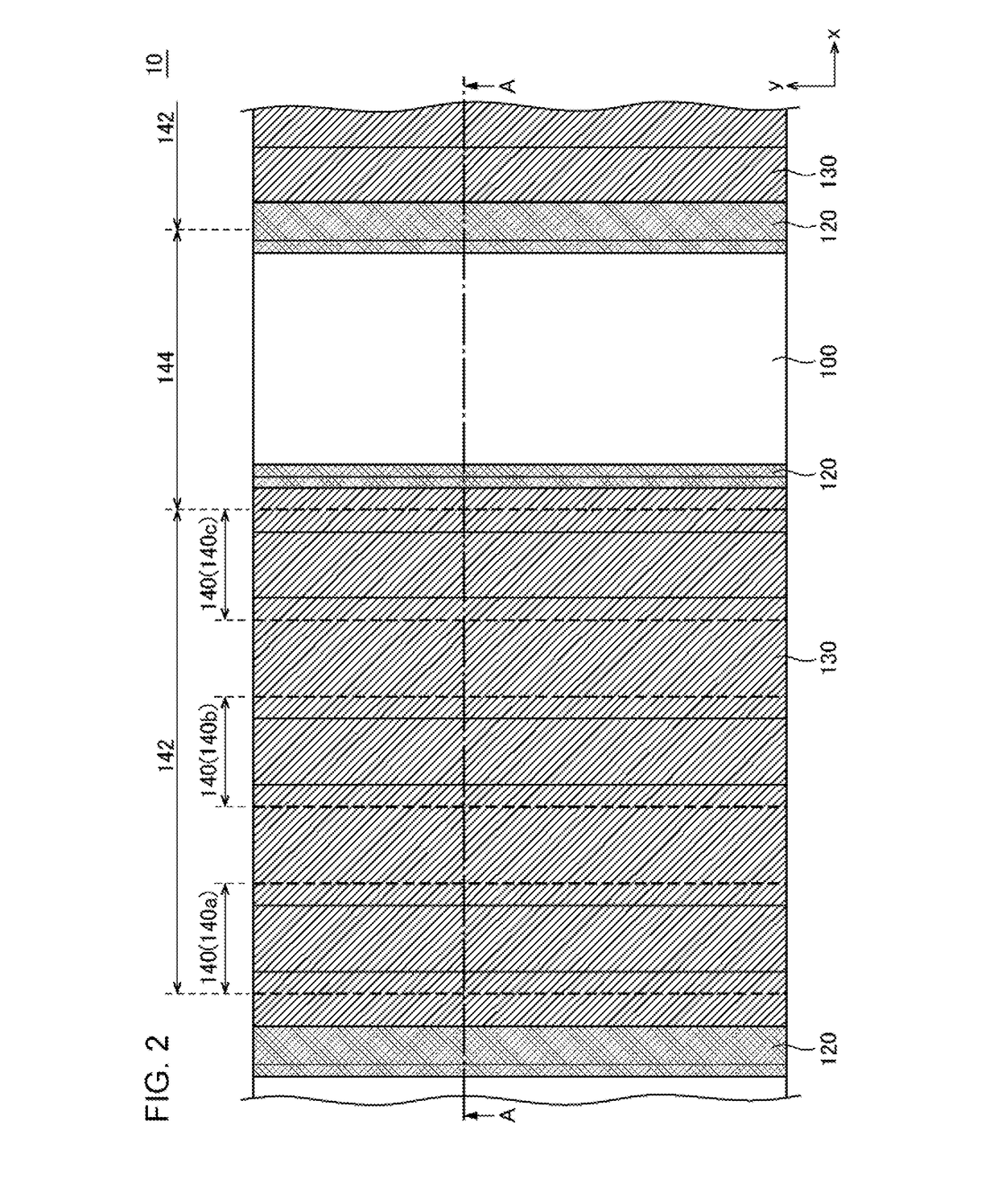
[0039]FIG. 3 is a cross-sectional view illustrating a light-emitting device 10 according to Modification Example 1, and corresponds to FIG. 1 in the embodiment. The light-emitting device 10 according to the present modification example has the same configuration as that of the light-emitting device 10 according to the embodiment, except that the second electrode 130 is provided for each light-emitting unit 140.

[0040]In the present modification example, as is the case with the embodiment, it is also possible to make the non-light-emitting region 144 wider, or make the light-emitting unit 140 wider compared to a case where the non-light-emitting region 144 is provided per each of plural light-emitting units 140.

Example

Modification Example 2

[0041]FIG. 4 is a cross-sectional view illustrating a light-emitting device 10 according to Modification Example 2. The light-emitting device 10 according to Modification Example 2 has the same configuration as that of the light-emitting device 10 according to the embodiment or Modification Example 1, except that no organic layer 120 is formed at least in a portion (for example, an entire portion) of the non-light-emitting region 144. FIG. 4 illustrates a case where the configuration is the same as that of the light-emitting device 10 according the embodiment.

[0042]In the present modification example, as is the case with the embodiment, it is also possible to make the non-light-emitting region 144 wider, or make the light-emitting unit 140 wider compared to a case where the non-light-emitting region 144 is provided per each of plural light-emitting units 140. Further, since no organic layer 120 is formed at least in a portion of the non-light-emitting region 14...


PUM


Abstract

A substrate (100) transmits visible light. Plural light-emitting regions (142) are located on the substrate (100) and are aligned in a first direction. A non-light-emitting region (144) is provided in each area between the plural light-emitting regions (142) and transmits visible light. Moreover, the light-emitting region (142) includes plural light-emitting units (140). The light-emitting units (140) are aligned in the first direction. In addition, each light-emitting unit (140) includes a first electrode (110), an organic layer (120), and a second electrode (130). The organic layer (120) is formed between the first electrode (110) and the second electrode (130).

Description

TECHNICAL FIELD[0001]The present invention relates to a light-emitting device.BACKGROUND ART[0002]In recent years, there has been progress in the development of light-emitting devices using organic EL. Such light-emitting devices are used as illumination devices or display devices and configured of an organic layer interposed between a first electrode and a second electrode. Generally, a transparent material is used for the first electrode, and a metal material is used for the second electrode.[0003]There is a case where transmittance of light from the outside (optical transparency) is required in the light-emitting device using the organic EL. For example, Patent Document 1 discloses making the second electrode linear in order to provide a display device using an organic EL with optical transparency. In this way, a portion where the second electrode is provided emits light, and a portion where the second electrode is not provided transmits light from the outside.[0004]In addition, ...

Claims


Application Information

Patent Timeline
IPC IPC(8): H01L51/52H01L27/32H05B33/08H01L51/00H05B44/00
CPCH01L51/5203H01L27/3244H05B33/0896H01L51/0097H01L51/5253H01L2251/5361H01L27/3204H01L2251/5338H01L2227/326H01L2251/558H10K59/35H10K77/111H10K50/11H10K2102/3023H10K2102/311H05B45/60H10K50/805H10K50/844H10K59/12H10K59/86H10K59/1201H10K71/80H10K2102/351
Inventor AOKI, KENJIMITO, NORIKAZUYUKI, TOSHINAO
Owner PIONEER CORP
Why Eureka
Try Eureka