
Signal delay apparatus for providing exact delay amount, memory apparatus utilizing the signal delay apparatus, and signal delay method

Active Publication Date: 2012-08-02
FARADAY TECH CORP
View PDF4 Cites 0 Cited by
  • Summary
  • Abstract
  • Description
  • Claims
  • Application Information

AI Technical Summary

Benefits of technology

[0007]Therefore, one of the objectives of the present invention is to provide a signal delay apparatus capable of providing an exact delay amount and capable of being controlled simply and a signal delay method thereof.
[0011]According to the aforementioned exemplary embodiments, the digitalization control circuit may provide an exact delay value, and may simultaneously utilize a plurality of delay circuits and a plurality of delay control signals to control respective delay circuits. Moreover, by utilizing this mechanism, the delay circuit may not be limited to be disposed close to the delay control circuit for decreasing interference between signal transmissions, thereby improving flexibility in circuit design and decreasing the circuit area.

Problems solved by technology

As a result, the signal channel lines, the power lines, the ground lines, etc. will be hard to place and route balanced, so there is a problem resulted from the mismatch between signal channel lines.
For example, it is difficult to control the analog signal.
When the compensation is realized by means of continuous try-and-error, it is time-consuming and requires a large circuit area.

Method used


Image

  • Signal delay apparatus for providing exact delay amount, memory apparatus utilizing the signal delay apparatus, and signal delay method
  • Signal delay apparatus for providing exact delay amount, memory apparatus utilizing the signal delay apparatus, and signal delay method
  • Signal delay apparatus for providing exact delay amount, memory apparatus utilizing the signal delay apparatus, and signal delay method

Examples


Embodiment Construction

[0020]Certain terms are used throughout the description and following claims to refer to particular components. As one skilled in the art will appreciate, manufacturers may refer to a component by different names. This document does not intend to distinguish between components that differ in name but not function. In the following description and in the claims, the terms “include” and “comprise” are used in an open-ended fashion, and thus should be interpreted to mean “include, but not limited to . . . ”. Also, the term “couple” is intended to mean either an indirect or direct electrical connection. Accordingly, if one device is electrically connected to another device, that connection may be through a direct electrical connection, or through an indirect electrical connection via other devices and connections.

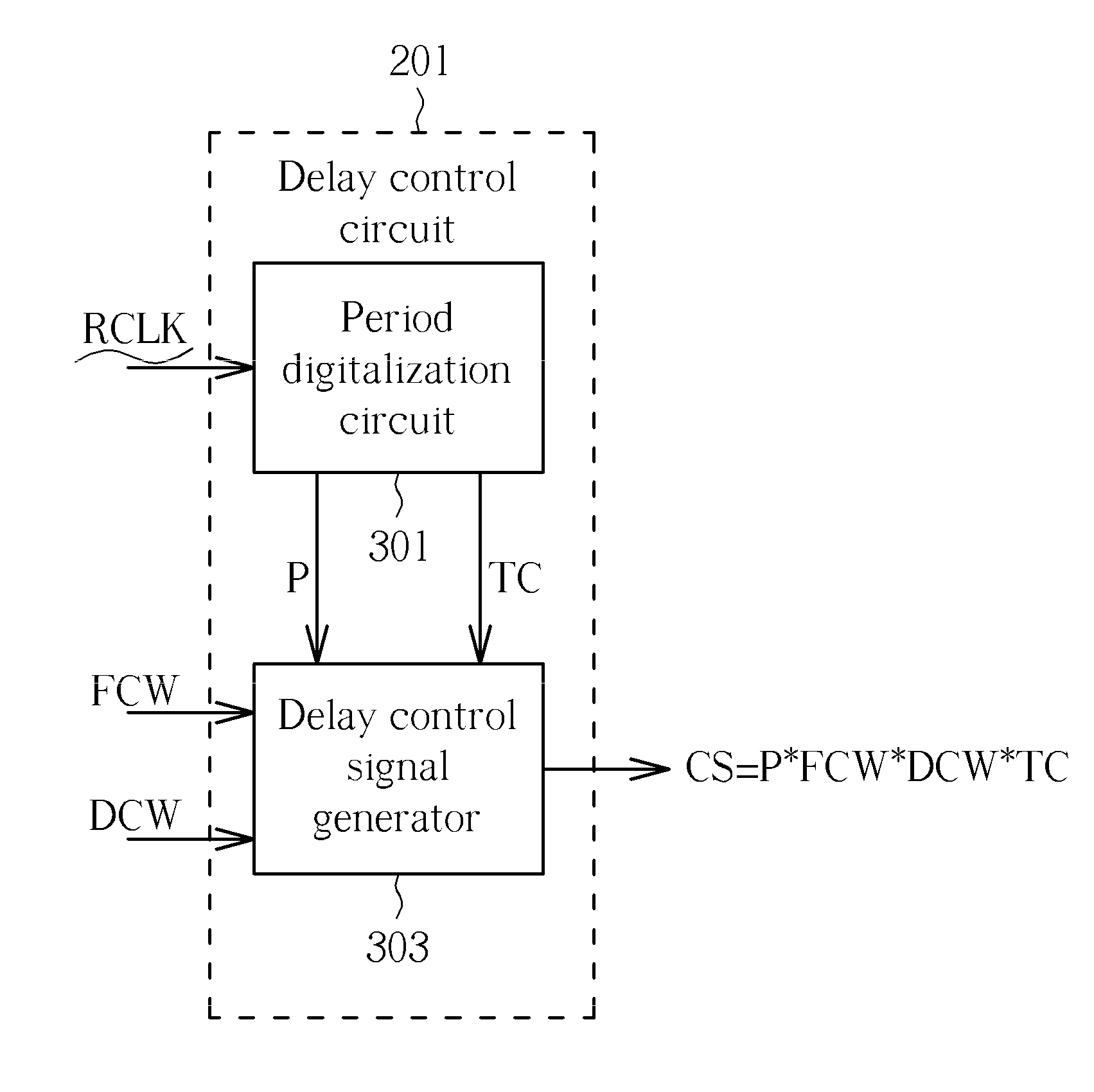
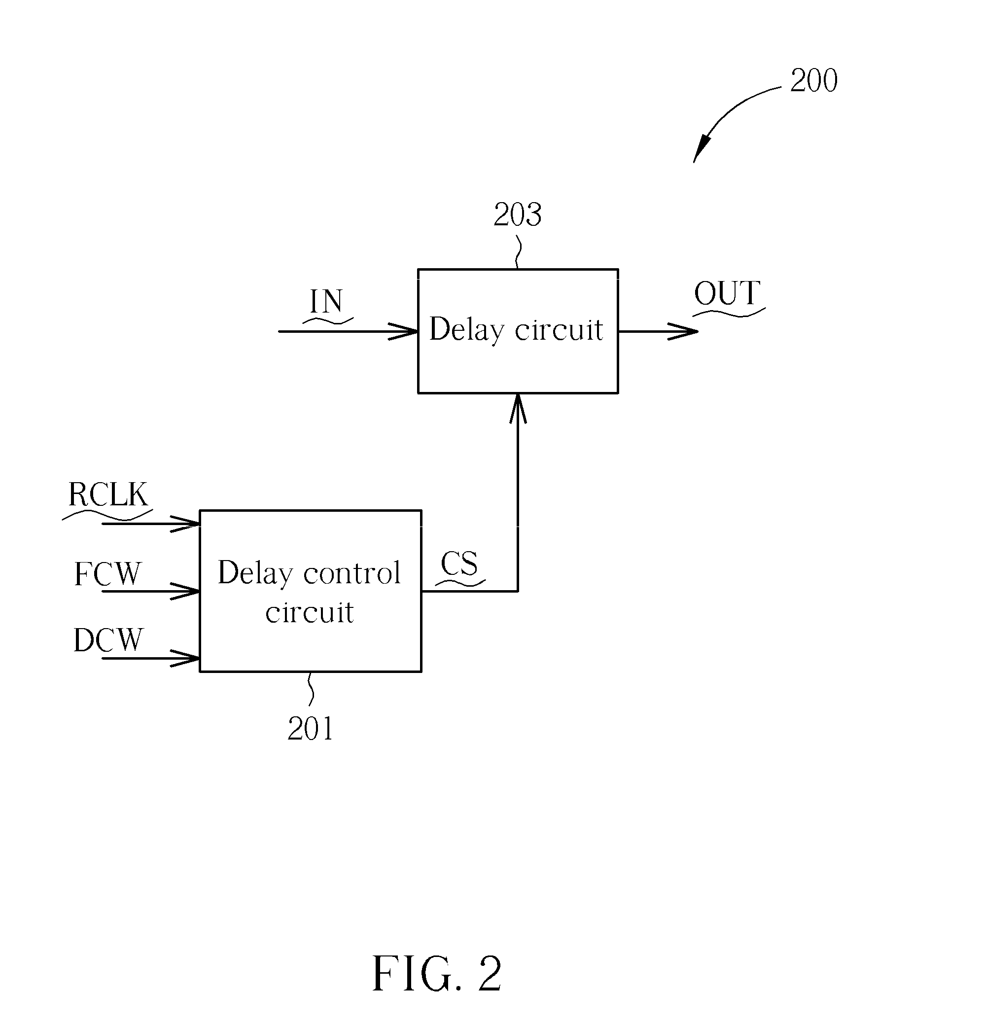
[0021]FIG. 2 shows a signal delay apparatus 200 according to an exemplary embodiment of the present invention. As shown in FIG. 2, the signal delay apparatus 200 includes a del...


PUM


Abstract

A signal delay apparatus, including: a period digitalization circuit, for digitalizing a period of a reference clock signal to generate a digitalized reference period; a delay control signal generator, for generating a delay control signal according to the digitalized reference period, a reference frequency and a required delay indicating signal; and a delay circuit, for delaying an input signal to generate an output signal according to the required delay control signal.

Description

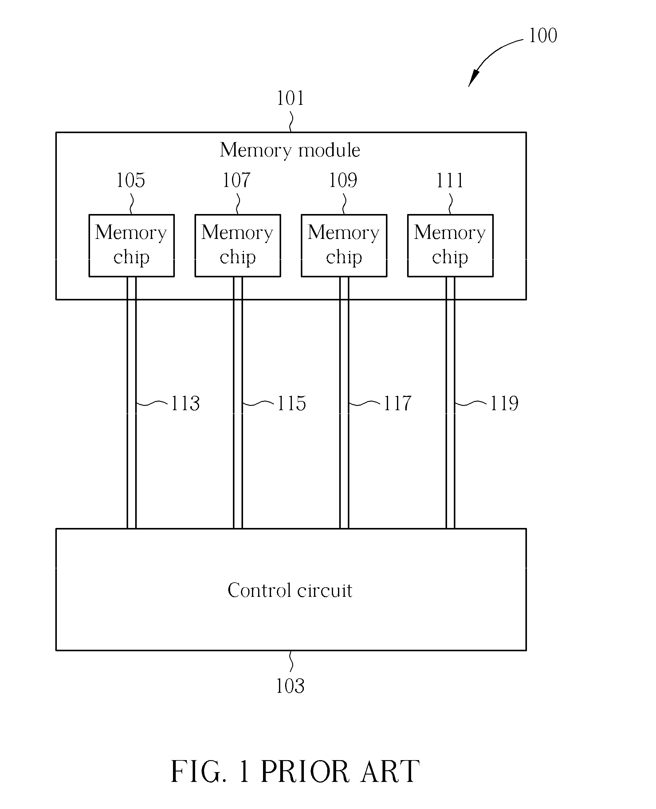
BACKGROUND OF THE INVENTION[0001]1. Field of the Invention[0002]The present invention relates to a signal delay apparatus, a memory apparatus that utilizes this signal delay apparatus and a signal delay method, and more particularly, to a signal delay apparatus capable of providing an exact delay amount, a memory apparatus that utilizes this signal delay apparatus and a signal delay method thereof.[0003]2. Description of the Prior Art[0004]FIG. 1 shows a memory apparatus 100 according to the prior art. As shown in FIG. 1, the conventional memory apparatus 100 includes a memory module 101 and a control circuit 103. The control circuit 103 accesses (reads / writes) the memory chips 105-111 via signal channels 113-119. In earlier electronic apparatuses, four-layer circuit boards are utilized, so there is enough room between each signal channel line, power line and ground line. Therefore, there is no problem resulted from mismatch between signal channel lines. However, in order to decreas...

Claims


Application Information

Patent Timeline
IPC IPC(8): H03L7/24H03H11/26
CPCH03L7/0814H03K5/135H03K5/133H03L7/0816
Inventor HUANG, YEN-YINLIN, CHIH-HSIENCHEN, CHAUO-MINYU, MING-SHIH
Owner FARADAY TECH CORP
Learn More