Electric motor control device, electric motor system and electric motor control method

a technology of electric motors and control devices, applied in the direction of dynamo-electric converter control, dc motor speed/torque control, angular speed control of ac motors, etc., can solve the problem of inability to achieve control for the purpose of targeting characteristics in control design

Active Publication Date: 2018-03-08
CANON KK
View PDF2 Cites 3 Cited by
  • Summary
  • Abstract
  • Description
  • Claims
  • Application Information

AI Technical Summary

Benefits of technology

[0007]a position detecting unit configured to detect a rotational phase of the electric motor and to output a detected signal; a speed detecting unit configured to detect information of a rotational speed of the electric motor based on the detected signal output by the position detecting unit; and a control unit configured to control a phase relationship between the rotational phase of the electric motor and a phase of the drive wavef...

Problems solved by technology

Thus, control for the purpose of targeted characteristics in control design cannot be realized in some cases when a relationship between the a...

Method used


Image

  • Electric motor control device, electric motor system and electric motor control method
  • Electric motor control device, electric motor system and electric motor control method
  • Electric motor control device, electric motor system and electric motor control method

Examples


example 1

[0050]A flow of a process in Example 1 of the present invention will be described with reference to flowcharts in FIGS. 7 and 8. A speed feedback (which is also referred to as an FB) process shown in FIG. 7 is assumed to be performed by the CPU 108 in a periodic process having a necessary and sufficient frequency.

[0051]After the speed FB process is started, in S701, the CPU 108 calculates a periodic count difference value. A latest cycle time corresponding to latest speed information which is currently detected is expressed as a variable CUR_SNS_TIME_CNT. A target cycle time of an ENC signal corresponding to a target speed is expressed as a variable TRGT_SNS_TIME_CNT. When a periodic count difference value is expressed as a variable ERR_SNS_TIME_CNT, the periodic count difference value is calculated using the following expression.

ERR_SNS_TIME_CNT=CUR_SNS_TIME_CNT−TRGT_SNS_TIME_CNT

[0052]The periodic count difference value is stored in a storage area of the variable ERR_SNS_TIME_CNT. ...

example 2

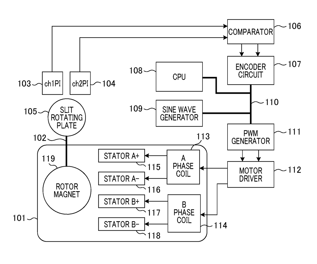
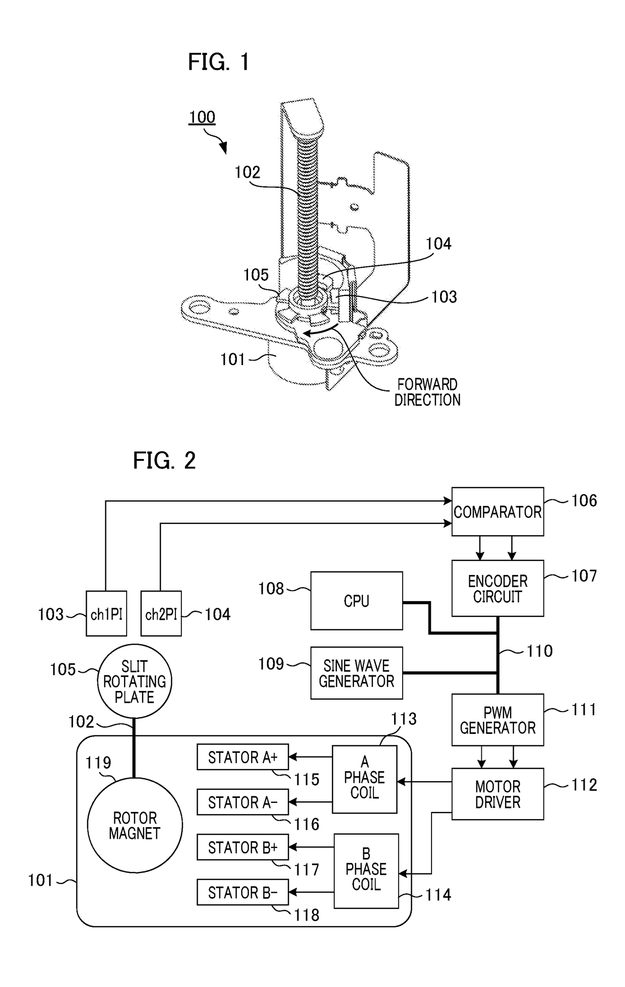
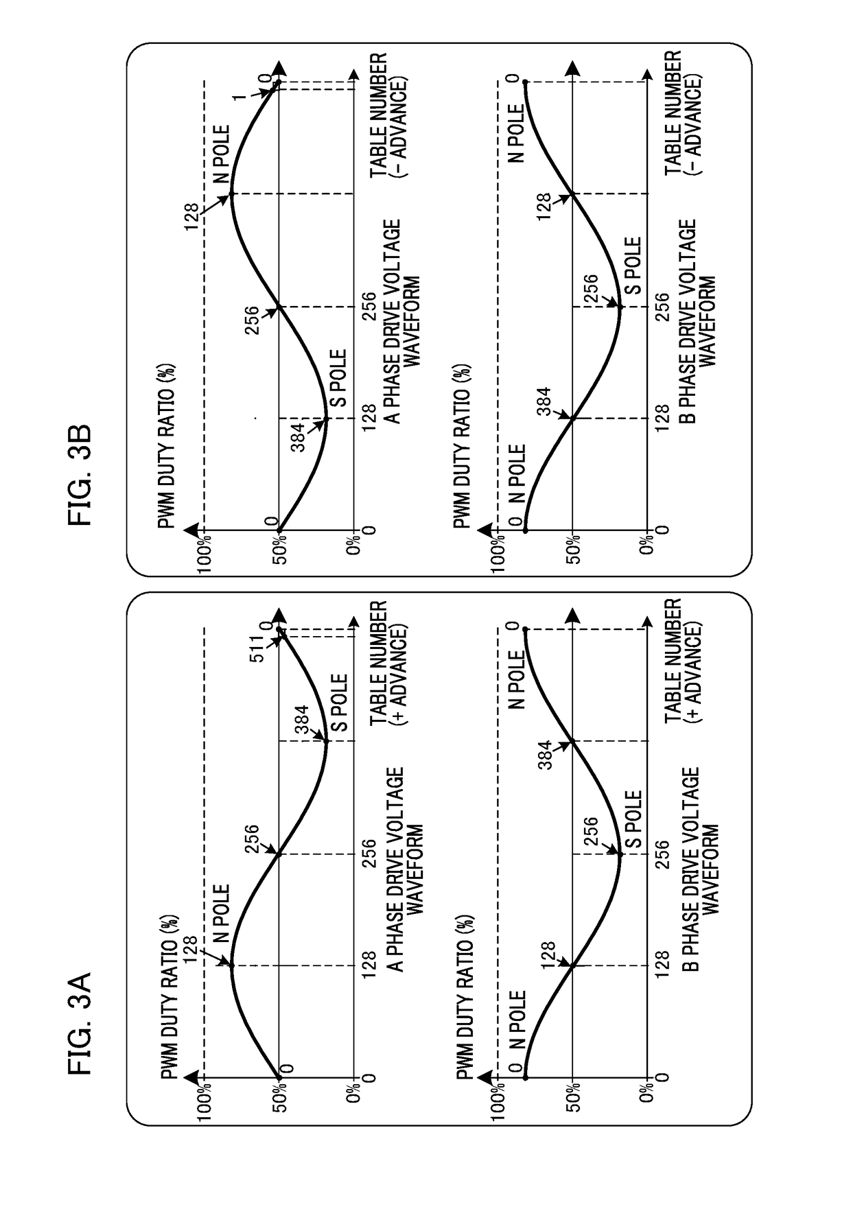
[0091]Next, Example 2 of the present invention will be described with reference to FIGS. 12A to 18. In Example 1, with regard to a voltage waveform, a process of correcting non-linearity between an amplitude setting value and an output value (an integrated value) is illustrated. In this example, a process of correcting non-linearity of output torque using an amplitude setting value and a relationship between a rotational phase of the rotor magnet 119 and a phase of a drive waveform is illustrated. For this reason, first, a principle explanation of changed content of the output torque due to a phase difference between the rotational phase of the rotor magnet 119 and the phase of the drive waveform will be provided using FIGS. 12A to 17A and 17B.

[0092]FIGS. 12A to 12E are diagrams for describing a mechanism of rotational torque generated due to excitation of the stators A+115. FIGS. 12A to 12D illustrate cases in which rotational phases of a rotor are 0°, 90°, 180°, and 270°. FIGS. 12...

modified example

[0108]In Examples 1 and 2, the description thereof has been given using a configuration in which a drive waveform of a pseudo-trapezoidal wave maybe used at all times when a speed is controlled. In a modified example, speed characteristics of an electric motor are individually acquired in advance and ON / OFF of speed control using a pseudo-trapezoidal wave is switched in accordance with a target rotation speed. Since careless use of a pseudo-trapezoidal wave is likely to affect vibrations and noise, as long as the motor can sufficiently reach a target rotation speed with a sine waveform-like drive waveform, the target rotation speed may be set in advance such that the process does not proceed to the process of S711 to S717 in FIG. 8.

[0109]In the modified example, the CPU 108 stores individual difference information of speed characteristics of the motor in a storage unit. It is assumed that the individual difference information is information representing a characteristic difference...


PUM


Abstract

An electric motor control device includes a drive waveform generating unit configured to generate a drive waveform (a sine wave or a pseudo-trapezoidal wave) to an electric motor. A plurality of photo interrupters detect a rotational phase of an electric motor, and a information of rotational speed is detected by an encoder circuit based on a detected signal of the rotational phase of the electric motor. The control unit controls the drive waveform generating unit on the basis of detection information of the rotational phase of the electric motor and performs control so that a phase relationship between the rotational phase of the electric motor and the phase of the drive waveform is kept constant. Furthermore, the control unit sets an amplitude value of the drive waveform generated by the drive waveform generating unit in accordance with a difference between a target speed and the detected information of rotational speed and performs speed control so that a speed of the electric motor is kept constant. The control unit calculates an amplitude setting value with which correction for suppressing non-linearity is performed in a region in which an amplitude setting value of the drive waveform and actual work given to the electric motor is non-linear and controls the speed.

Description

BACKGROUND OF THE INVENTIONField of the Invention[0001]The present invention relates to speed control according to a change in shape of a drive waveform with respect to an electric motor.Description of the Related Art[0002]Control techniques in stepping motors include a technique for realizing high efficiency driving or high speed driving on the basis of a rotational position detected using a mechanism configured to detect a rotational position of a rotor. According to this technique, stepping motors behave similarly to direct current (DC) motors, a speed is increased when a load is lowered, and the speed is decreased when the load is increased. A speed of the motor at a time of high speed driving can be controlled by increasing and decreasing an amount of input voltage.[0003]Japanese Patent Laid-Open No. 2014-45646 includes installing two sensors configured to be exchanged between two values depending on rotation of a motor shaft, identifying a magnetized phase of a rotor magnet fr...

Claims


Application Information

Patent Timeline
IPC IPC(8): H02P7/30H02P6/08H02P7/02H02P23/18
CPCH02P7/305H02P6/08H02P2209/11H02P23/18H02P7/02H02P8/18
Inventor MIZUO, YOSHIHIRO
Owner CANON KK
Why Eureka
Try Eureka