
Motion detecting apparatus and motion detecting system

Inactive Publication Date: 2018-03-08
SEIKO EPSON CORP
View PDF2 Cites 4 Cited by
  • Summary
  • Abstract
  • Description
  • Claims
  • Application Information

AI Technical Summary

Benefits of technology

The motion detecting apparatus described in this patent has several technical effects. First, it increases the space between the antenna and other components, reducing the impact of noise on the signals transmitted by the inertial sensor and electronic part. Second, it allows the user to be further away from the battery, reducing the impact of heat on the user's experience. Additionally, even when the motion detecting apparatus and the notification apparatus are placed close to each other, the system still performs stable wireless communication between the two.

Problems solved by technology

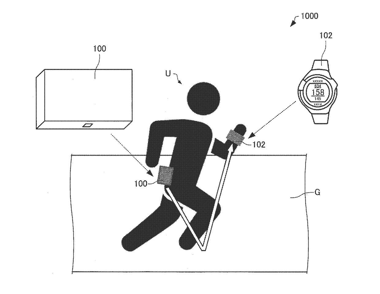
In the motion analyzing system (motion detecting system) described above, however, for example, in a case where the wrist around which the electronic module is worn is in a position in the user's traveling direction (in front of user), the user's body is present between a motion detecting apparatus including the sensor and worn on the waist and the electronic module, so that the wireless communication between the motion detecting apparatus and the electronic module is unstable in some cases.
As a result, in the motion detecting apparatus, rust and other undesirable phenomena due to sweat of the user, rainwater, and other objects is unlikely to occur.

Method used


Image

  • Motion detecting apparatus and motion detecting system
  • Motion detecting apparatus and motion detecting system
  • Motion detecting apparatus and motion detecting system

Examples


Embodiment Construction

[0041]A preferable embodiment of the invention will be described below in detail with reference to the drawings. It is not intended that the embodiment described below unduly limits the contents of the invention set forth in the appended claims. Further, all configurations described below are not necessarily essential configuration requirements of the invention.

1. Motion Detecting Apparatus

[0042]The following description will be made with reference to a motion detecting apparatus that detects a physical quantity based on motion in a user's running activity (including walking activity), but the motion detecting apparatus according to the present embodiment can also be used as a motion detecting apparatus that detects a physical quantity based on motion other than running activity.

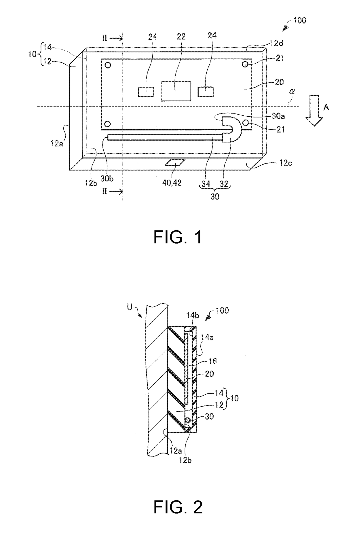
[0043]The motion detecting apparatus according to the present embodiment will first be described with reference to the drawings. FIG. 1 is a perspective view diagrammatically showing a motion detecting appar...


PUM


Abstract

A motion detecting apparatus includes an inertial sensor and an antenna via which a signal containing information based on data outputted from the inertial sensor is transmitted to a notification apparatus attached to a user, and when the motion detecting apparatus is attached to the user, at least part of the antenna is located on a ground side.

Description

BACKGROUND1. Technical Field[0001]The present invention relates to a motion detecting apparatus and a motion detecting system.2. Related Art[0002]In recent years, a motion analyzing system that analyzes motion is required in a variety of fields. JP-A-2013-233342, for example, describes that an activity quantity meter including a display section is attached to the waist of a person's body by sandwiching a belt, a waist band of trousers, or any other object between an attachment member and a main body of the activity quantity meter. Further, JP-T-2012-524640 describes an electronic module (wristwatch) that wirelessly communicates with a sensor (heart rate monitor, for example) worn on a user, is worn around the user's wrist, and has a display function.[0003]In the motion analyzing system (motion detecting system) described above, however, for example, in a case where the wrist around which the electronic module is worn is in a position in the user's traveling direction (in front of us...

Claims


Application Information

Patent Timeline
IPC IPC(8): H04Q9/00H01Q1/27A61B5/11A61B5/00
CPCH04Q9/00H01Q1/273A61B5/11A61B5/6824A61B5/74A61B5/6823H04Q2209/43G01P15/02G01C19/00A61B2562/0219A61B5/7405A61B5/7455A61B2503/10A61B2505/09
Inventor WATANABE, KEN
Owner SEIKO EPSON CORP
Learn More